
Manual
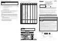

3. Part Names and Dimensions
Guard
Reflector
Bulb
Name Plate
Glass Globe
Acrylic Globe
Bracket
(Main Unit Cover)
Terminal Box Cover
4. Installation and Wiring
Caution
<Accessory>
<Mounting Dimension Drawing>
“Easy Lever”
Hex Wrench
External Connection Terminal
(Grounding Terminal)
Mounting Hole
4-φ9
Keylock
Hex Bolt for
Keylock
Terminal Box Cover
Globe Frame
(The line cable is
connected here)
Terminal
Terminal Setscrew
(M4)
Junction Box
• Request a special contractor to install and wire this product in accordance with the "User's factory explosion
prevention electricity equipment guide" from the Technology Institution of Industrial Safety.
• The terminal wiring is specified as the white wire is positive, and the black wire is negative for the DC12V, 24V
and 48V models. Verify the proper working voltage is connected.
• When wiring, use a conduit size of G3/4 and pressure-resistant metallic fittings (pressure-resistant sealing
cable glands). Ensure waterproofing has been done to the connection threads.
• For pressure-resistant metallic seals (pressure-resistant sealing cable glands), use our optional products
(officially approved) available separately. Pressure-resistant sealing cable glands from other companies
cannot be used.
• Avoid mounting this product in a location with direct vibrations and shock. If mounted where vibration is
intense, the lifespan of the electric bulb becomes shorter. In additon, the mounting location should be selected
where strong winds, vibration, etc. does not cause it to shake.
• When installing the product in a high place, choose a place where it is accessable by a ladder or scaffold to
perform inspection or maintenance.
• Only remove the terminal box cover when wiring, and do not scratch or damage the terminal box cover nor the
flat connection part of the bracket. If a crack, dent, etc. occurs, it loses the explosion proof capability.
• The cross section of the electric wire to be used, should be no less than 2.5 mm
2
.
<Installation>
1. Refer to the mounting dimension figure when making the mounting holes.
2. Use M8 nuts and bolts when installing.
<Wiring>
1. Use the hexagon wrench supplied to remove the bolts to the terminal box cover (four places).
2. Please connect the wiring to the Terminal Buss with the "easy lever" supplied, and ensure the proper polarity is
connected. Connect the earth-ground wire to a grounding terminal.
- A small flat-head screwdriver or flathead screwdrivers indicated by the following manufacturers can be
substituted for the "Easy Lever".
Phoenix Contact Corporation Part Number: SZF0
WAGO Corporation Part Number: 210-120J
3. When the cable wiring within the terminal box is completed, fasten the terminal box coverwith the bolts, and use
the hexagon wrench to tighten the bolts, then secure the bracket. Do not remove the attached O-ring (rubber
packing).
5. Maintenance/Inspection
• Lamp or Dome replacement is to be done by an operator who received the proper training, and has been given
permission from a supervisor, and done after the power has been disconnected for 30 minutes or more.
• The bulb is to be replaced with an equivalent value indicated in this manual, or where it is indicated on the name
plate. If an electric bulb other than what is specified is used, an increase in the outer temperature could exceed
the rated value for the ignition point, causing an accidental explosion where the surrounding gas is present.
• Use this product within the ambient temperature limits and environment defined in this manual.
• Do not operate this product with the dome (body cover) removed.
• Do not apply oil to the motor or rubber belt. (The motor will stop rotating if oil enters it.)
Warning
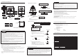
<Wiring Procedure>
Driver Insertion Slot
Wire Insertion Hole
Cabtyre Cable
Wire Conduit
Pressure-resistant Sealed Metal Fittings
(Pressure-resistant Sealed Cable Gland)
Sealing Fitting Bracket
Wire Insertion Hole
(Grounding Terminal)
Internal
Connection Terminal
※Strip the wire.
Wire
Wire
Terminal Buss
“Easy Lever”
Lead
Wire
(Attention)
The cable wires should have a
cross-sectional area of no less than
2.5 mm
2
.
(Attention)
※Water-proof the threading area for the electric wire
conduit and pressure-resistant seals.
Screw Thread: G3/4
Pitch: 1.81432
※ For DC Type
7. Specifications
(1) Cable Wire Connection
(2) Electric Wire Conduit Connection
(1) Push downward on the lever and insert the wire into
the slot from an angle, using the "easy lever" or
appropriate driver.
● Be careful when handling the "easy lever" it may be
sharp.
(2) Insert the stripped part of the electric wire fully into
the slot.
(3)
- Pull the "easy lever" out of the slot.
- Check that the electric wire is securly fixed to the
Terminal Buss.
- After connecting the electric wire into the terminal
box, store any extra electric wire inside the crevices.
<Wiring Reference Diagram>
※ Some specifications may change for improvements, etc., without prior notice.
6.Options and Replacement Parts
Various replacement parts and options are available.
• Option (Example: cable line construction)
Pressure-resistant metal seals (Pressure-resistant Cable Gland)
1. Compatible Cable Phi7.4-Phi12
Code: A28220003
2. Compatible Cable Phi12-Phi16
Code: A28220002
• Replacement Parts
- Dome (Resin) - Reflector
- Electric Bulb - Accessories
Caution
• Maintenance and inspection should follow the "User's guide for factory explosion proof electric installation"
from the Technology Institution of Industrial Safety.
• Do not attempt to modify or change any parts.
• To extend the service life of this product, perform perodic inspections and pre-maintenance. Prior to
maintenance checks turn off the power.
• Wipe off any accumulated dirt of the resin dome and glass dome with a soft cloth moistened with water.
<Electric Bulb Replacement>
1. Wait 30 minutes or more after disconnecting the power supply.
2. Remove the hexagon bolts with the hexagon wrench accessory. The dome frame (body cover) is secured with a
bracket, and by firmly holding the dome frame (body cover) or guard and turning in a counterclockwise direction,
the globe frame (body cover) can be removed.
3. The resin globe can be removed by turning it counterclockwise.
4. To remove the electric bulb, push down and turn counterclockwise.
5. To install a new electric bulb, push down and turn in the clockwise direction.
6. Turn the resin globe clockwise to re-attach it.
7. Turn the globe frame (body cover) clockwise to re-attach it to the bracket. Do not remove the O-ring (rubber
packing) from the bracket.
8. Attach the key lock.
● If there are any questions regarding this product, please contact your nearest PATLITE representative.
Wire
Terminal No.
Polarity
Black 2 Negative
White 1 Positive
Product
RES-12A RES-24A RES-48A RES-100A RES-120A RES-220A RES-240A
Rated Voltage
DC12V DC24V DC48V
AC100 - 110V AC115 - 120V AC200 - 220V AC230 - 240V
50/60 Hz
Operating Voltage Range
DC9.5 - 15V DC20 - 30V DC38 - 53V AC100 - 110V AC115 - 120V AC200 - 220V AC230 - 240V
Rated Current
0.9A 0.6A 0.3A 0.1A 0.1A 0.05A 0.05A
Flash Rate
170 rpm 150 rpm 170 rpm
Rotating Direction
Clockwise
Bulb Type
12V 10W 24V 10W 48V 10W 12V 10W
Base: BA15S Bulb: G18
Operating Temperature Range
-20
o
C to +55
o
C-20
o
C to +60
o
C
Atmospheric Pressure
Atmospheric Pressure: 80 - 110kpa
Relative Humidity
Relative Humidity: 45 - 80%
Mounting Direction
Indoors: Upright, Sideways, Upside-down Outdoors: Upright
Protection Rating
IP65
Vibration Resistance
44.1m/s
2
(Passes JIS D 1601-1990 Level 4 Class 3/Type B)
Insulation Resistance
More than 1Mohm at DC500V between a power supply terminal and the chassis
Withstand Voltage
The following voltage is applied for 1 minute between a power supply terminal and
the chassis without breaking insulation.
AC 1,000V AC 1,500V
Illumination
8000cd 5200cd 4800cd 3340cd
Spare Bulb
None
Mass
6.5kg
130
130
12
1 2
296
227
φ214
8~9mm