
Installation Instructions

SAFETY INFORMATION
PREPARATION
ASSEMBLY INSTRUCTIONS
Please read and understand this entire manual before attempting to assemble, operate or install the product.
WARNING
• Turn off electricity at main fuse box (or circuit breaker box) before beginning installation by removing fuse (or switching
off circuit breaker).
• Be careful not to damage or cut the wire insulation (covering) during fixture installation. Do not permit wires to contact
any surface having a sharp edge. To do so may damage or cut the wire insulation, which could cause serious injury or
death from electric shock.
CAUTION
• All electrical connections must be in agreement with local codes, ordinances or the national electric code (NEC).
Contact your municipal building department to learn about your local codes, permits and/or inspections. If you do not
have electrical wiring experience, refer to a do-it-yourself wiring handbook or have your fixture installed by a qualified
licensed electrician.
• Risk of fire – most dwellings built before 1985 have supply wire rated for 140°F/60ºC. Consult a qualified electrician
before installation.
• Do not exceed the recommended wattage. Refer to the re-lamping label on the light socket for maximum wattage.
• Do not replace a bulb when electrical outlet switch is turned to the “ON” position.
• Do not immerse your lamp in water; doing so will damage the wire.
• Keep materials that burn easily away from lighted bulbs.
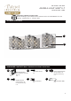
Before beginning assembly, installation or operation of product, make sure all parts are present. Compare parts with
package contents list and diagram on previous page. If any part is missing or damaged, do not attempt to assemble,
install or operate the product. Contact customer service for replacement parts.
Tools Required for Assembly (not included): Screwdriver, Phillips Screwdriver, Pliers, Electrical Tape, Wire Cutters, Safety
Glasses, Ladder, Wire Stripper.
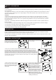
1. Unscrew the support screws (DD)
from the mounting bracket (AA).
Remove the mounting bracket (AA)
from the fixture body (A), and keep
the support screws (DD) for later use.
3. Strip 3/4 in. of insulation from wire ends. Connect the black wire from the fixture body
(A) to black wire from the outlet box, the white wire from the fixture body (A) to white wire
from the outlet box, and the bare copper ground wire from the fixture body (A) to ground
wire from the outlet box with the wire connector (EE), The bare copper ground wire from the
fixture body (A) must loop one turn under the head of green screw (CC) on mounting bracket
(AA) before it is connected to the ground wire from the outlet box. Cover the wires with wire
connectors (EE). Tape the wire connectors (EE) and wires together, and carefully position all
wires inside the outlet box.
2. Fasten the mounting bracket (AA)
onto the outlet box using two outlet
box screws (BB).
4. Place the fixture body (A) against
the outlet box, align the two holes of
the mounting bracket (AA) and fixture
body (A), then tighten the support
screws (DD).
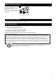
5. Install the light bulbs (FF) in the
sockets. Use 3 X 40Watt Max G9
base xenon bulbs (included).
Note:
Use only Max 40W type G9
xenon bulb, DO NOT use type G9
halogen bulb without shield.
Note:
Do not touch the G9 xenon
bulbs with bare hands at any time.
A pair of white gloves has been
included for installation as oil from
the skin may damage the bulb.
Note:
Please remove the protective
film from the fixture body (A) before
installing the bulbs (FF).
2
1
3
2
45
A
FF
BB
AA
AA
EE
CC
AA
AA
A
A
A
DD
DD