52” MILLER STATION CEILING FAN Owner’s Manual Model #20681 SKU #355-0647 If a problem cannot be remedied or you are experiencing difficulty in installation, please contact the Service Department: 1-877-459-3267, 8 a.m. - 5 p.m. Central Time, Monday - Friday.
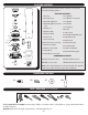
PACKAGE CONTENTS Unpack your fan and check the contents. You should have the following items: 1 2 4 1. Canopy 3 5 6 8 9 PACKAGE CONTENTS 15. Light Pan 7 16. Light Pan Screw (x3) 3. Mounting Bracket 17. Light Kit 4. Mounting Bracket Screw 18. Hex Nut (x4) 19. Finial Cap 5. Downrod 20. Finial 10 6. Downrod Pin 24 11 2. Canopy Cover 7. Downrod Clip 12 14 13 8. Yoke Cover 9. Set Screw (x2) 15 16 17 23 18 20 19 21 22 25 18 16 10. Closemount Screw (x3) 11. Motor Assembly 12.
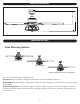
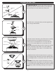
DIMENSION REFERENCE C B A A. 16.9 in. B. 10.93 in. C. 5.13 in. MOUNTING OPTIONS Three Mounting Options Closemount Downrod Mount Angled Ceiling Mount (Up to 16 degrees) Choose one of the following mounting options: Closemount is best suited for ceilings lower than 8 feet. It does not utilize the downrod. Downrod Mount is best suited for ceilings 8 ft. or higher. For taller ceilings you may want to use a longer downrod (not included). Angled Ceiling Mount is best suited for angled or vaulted ceilings.
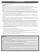
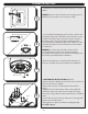
SAFETY INSTRUCTIONS READ ALL SAFETY INFORMATION AND INSTALLATION INSTRUCTIONS BEFORE YOU BEGIN INSTALLING THE FAN AND SAVE INSTRUCTIONS. CAUTION: All set screws of the fan must be checked and retightened where necessary before installation. To reduce the risk of personal injury, do not bend the blade brackets when installing the brackets, balancing the blades or cleaning fan. Do not insert foreign objects in between rotating fan blades.
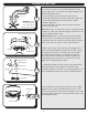
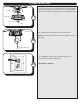
ASSEMBLY INSTRUCTIONS 1. Turn OFF the electrical power at the main fuse or circuit breaker. 1 Mounting Bracket Screw 2 DANGER: Failure to disconnect the power supply prior to installation may result in serious injury or death. 2. Loosen all four mounting bracket screws located on the mounting bracket and completely remove the two screws from the round holes in the canopy. Save the screws for later. Remove the canopy from the mounting bracket.
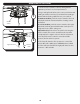
ASSEMBLY INSTRUCTIONS Downrod 5. DOWNROD MOUNT - Remove the downrod clip and downrod pin from the downrod. Then, loosen but don’t remove the two set screws at the top of the yoke. Downrod Clip Downrod Pin Set Screw 5 Yoke 6. Feed the wires coming from the yoke through the yoke cover, canopy and downrod. Downrod Canopy Yoke Cover 6 Yoke 7 7. Slide the downrod into the yoke of the motor assembly, align the holes, then re-install the downrod pin and downrod clip.
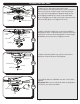
ASSEMBLY INSTRUCTIONS 9. Use wire connectors to connect the fan wires to the power supply wires according to the wiring diagram and the following instructions: Black (Hot) White (Neutral) Bare/Green (Ground) 9 Green White Black Blue Wire Connector WARNING: Do NOT wire the fan motor to a variable-speed (dimmer) wall control. Note: If there is a second hot/power wire coming from the outlet box, connect it to the blue (light power) fan wire for separate light and fan control.
ASSEMBLY INSTRUCTIONS Fitter Plate Light Pan 9-pin Connector 13 Fitter Plate Screw Light Pan Screw 9-pin Connector Light Pan 13. Remove one of the three fitter plate screws preassembled to the fitter plate and loosen the other two but do not remove. Feed the 9-pin connector through the center hole in the light pan. Align the keyhole slots in the light pan with the loosened screws in the fitter plate. Turn light pan clockwise and replace the previously removed fitter plate screw. Tighten all screws.
ASSEMBLY INSTRUCTIONS 17. Lift the wire cage over the threaded rod of the light kit and secure with the previously removed hex nut. Lift the finial cap onto the threaded rod and secure with the finial. Light Kit 17 Wire Cage Finial Cap Hex Nut Finial 18. Attach pull chain extensions to the pull chains. Note: The pull chain in the center of the light kit controls the light. 18 Pull Chain Extension 19. Turn ON the electrical power at the main fuse or circuit breaker and the wall switch.
OPERATING INSTRUCTIONS 1. Use the reverse switch, located on the light kit to optimize your fan for seasonal performance. 1 Reverse Switch In warmer weather, push the reverse switch to the left which will result in downward airflow creating a wind chill effect. In cooler weather, push the reverse switch to the right which will result in upward airflow that can help move stagnant, hot air off the ceiling area.
TROUBLESHOOTING If you have difficulty operating your new ceiling fan, it may be the result of incorrect assembly, installation or wiring. In some cases, these installation errors may be mistaken for defects. If you experience any faults, please check the Troubleshooting section below. If a problem cannot be remedied or you are experiencing difficulty in installation, please contact the Service Department: 1-877-459-3267, 8 a.m. - 5 p.m. Central Time, Monday - Friday.
LIMITED LIFETIME WARRANTY To obtain Service, please contact the Service Department: 1-877-459-3267, 8 a.m. - 5 p.m. Central Time, Monday - Friday.