
Installation Instructions

ASSEMBLY INSTRUCTIONS
Before beginning assembly, installation or operation of product, make sure all parts are present. Compare parts with package contents
list and diagram on previous page. If any part is missing or damaged, do not attempt to assemble, install or operate the product.
Contact customer service for replacement parts.
Estimated Assembly Time: 15 minutes
Tools Required for Assembly (not included): Screwdriver, Phillips Screwdriver, Pliers, Electrical Tape, Wire Cutters, Safety Glasses,
Ladder, Wire Stripper
PREPARATION
• All electrical connections must be in agreement with local codes, ordinances or the national electric code (NEC). Contact your
municipal building department to learn about your local codes, permits and/or inspections.
• Risk of fire – most dwellings built before 1985 have supply wire rated for 140°F/60ºC. Consult a qualified electrician before
installation.
• Do not connect this fixture to an electrical system that does not provide a means for equipment grounding. Never use a fixture in a
two-wire system that is not grounded. If you are not sure your lighting system has a grounding means, do not attempt to install this
fixture. Contact a qualified, licensed electrician for information with regards to proper grounding methods as required by the local
electrical code in your area
• If a dimmer control switch is used with this fixture, obtain professional advice to determine the correct type and electrical rating
required.
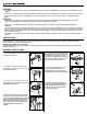
CAUTION
WARNING
•
Turn off electricity at main fuse box (or circuit breaker box) before beginning installation by removing fuse (or switching off circuit
breaker).
• Be careful not to damage or cut the wire insulation (covering) during fixture installation. Do not permit wires to contact any surface
having a sharp edge. To do so may damage or cut the wire insulation, which could cause serious injury or death from electric
shock.
Please read and understand this entire manual before attempting to assemble, operate or install the product.
3
4
4. Connect the black to black (power), the
white to white (neutral) and copper wire to
ground wire with the supplied wire nuts (DD)
and secure with electrical tape. Helpful Hint: If
wires out of the fixture are the same color,
attach the side with markings or letters to
black (positive) and the other to white
(neutral).
3. Connect the ground wire to the
mounting unit (AA) by securing it with the
preinstalled ground screw.
2. Attach mounting unit (AA) to the
junction box with the two mounting
screws (BB) as shown.
1. Screw the support screws (CC) into the
the mounting unit (AA).
5
6
7
6. Screw the pipe nipple (EE ) into the
light fixture (A) and secure with
preinstalled nut. Install 2 x 100W max
(medium) base bulbs (bulbs not included)
7. Secure the shade (B) to the light
fixture (A) by placing the shade (B) over
the pipe nipple (EE) followed by the
washers (FF) and (GG),hex nut (HH),
cover (D) and finial (C).
5. Line up the holes in the light fixture (A)
with the support screws (CC) and rotate
the light fixture (A) until the mounting
screws (CC) are aligned with the smaller
section of the mounting hole as shown.
Secure the support screws (CC).
1
2