
Installation Instructions


Before beginning assembly, installation or operation of product, make sure all parts are present. Compare parts with
package contents list and diagram on previous page. If any part is missing or damaged, do not attempt to assemble,
install or operate the product. Contact customer service for replacement parts.
Tools Required for Assembly (not included): Screwdriver, Phillips Screwdriver, Pliers, Electrical Tape, Wire Cutters,
Safety Glasses, Ladder, Wire Stripper.
Page 2 of 4
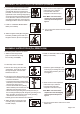
SAFETY INFORMATION
PREPARATION
• All electrical connections must be in agreement with local codes, ordinances or the national electric code (NEC).
Contact your municipal building department to learn about your local codes, permits and/or inspections.
• Risk of fire – most dwellings built before 1985 have supply wire rated for 140°F/60ºC. Consult a qualified electrician
before installation.
• Do not connect this fixture to an electrical system that does not provide a means for equipment grounding. Never use
a fixture in a two-wire system that is not grounded. If you are not sure your lighting system has a grounding means, do
not attempt to install this fixture. Contact a qualified, licensed electrician for information with regards to proper
grounding methods as required by the local electrical code in your area.
• If a dimmer control switch is used with this fixture, obtain professional advice to determine the correct type and
electrical rating required.
Please read and understand this entire manual before attempting to assemble, operate or install the product.
WARNING
•
Turn off electricity at main fuse box (or circuit breaker box) before beginning installation by removing fuse (or switching
off circuit breaker).
• Be careful not to damage or cut the wire insulation (covering) during fixture installation. Do not permit wires to contact
any surface having a sharp edge. To do so may damage or cut the wire insulation, which could cause serious injury
or death from electric shock.
CAUTION
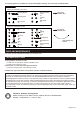
ASSEMBLY INSTRUCTIONS (FOR PENDANT)
Turn off the power at fuse or circuit box.
3. Remove the canopy from the stem
of the fixture. Attach the mounting
strap (PP) to the outlet box by using
two mounting screws (QQ).
1
3
2
JJ
4. Slip the nipple , secure it with
loop(JJ).
A
OO
GG
KK
PP
II
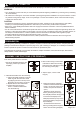
5
5. - Determine length of chain(KK)
needed to achieve desired fixture
height. (To remove excess chain
section, use pliers to bend link
open.)
- Weave the fixture wires and
fixture grounding wire through
the chain(KK) and the canopy(NN)
-Connect the chain(KK) to the
collar(OO dna ) the top loop on the
mounting strap(PP) using the two
loop locks(GG).
- Thread the fixture wires and
fixture grounding wire through the
center of the mounting strap(PP).
1
4
MM
LL
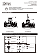
2. Install the silhouettes onto the metal ring.
a. Take a silhouette and place it onto the
metal ring with the hole in the metal
ring aligning the slot in the clip of the
silhouette, secure it with a set screw.
b. Repeat with the other silhouettes.
c. Please follow the sequence
shown to install the silhouettes
onto the metal ring.
HH
JJ
II
QQ
PP
RR
1. Secure the threaded pipe(HH) with
top loop(II), washer (LL) and hex
nut(MM).
End Cap
Set Screw
Clip
Metal Ring
P-C
P-C
P-C
P-C
P-C
P-B
P-B
P-C
P-R
P-C
P-R
P-B
NN