
Installation Instructions


4
ASSEMBLY INSTRUCTIONS (continued)
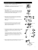
7.
Remove socket ring (GG) from the socket on fixture (C). Attach shade (D)
to the socket using socket ring (GG).
10.
bulb
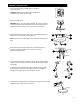
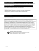
Make wire connections with wire connectors (EE) provided as follows:
Connect the BLACK wire from fixture to BLACK wire from outlet box.
Connect the WHITE wire from fixture to WHITE wire from outlet box.
Connect BARE ground wire from fixture to BARE/GREEN ground wire
from outlet box.
Note: If your outlet box wiring does not have a BARE/GREEN ground
wire, the BARE ground wire from fixture should be attached to the
GREEN SCREW labeled GND on the mounting plate.
Note: Screw wire connectors (EE) on in a clockwise direction.
WARNING: Never connect ground wire to WHITE or BLACK power
supply wires.
8.
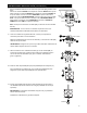
Wrap all wire connectors with electrical tape as an extra safety measure.
Carefully arrange excess wiring and wire connectors (EE) within outlet
box.
WARNING: Make sure no bare wire or wire strands are visible after
making connections.
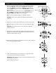
Align holes in canopy (A) with screws (BB) on mounting strap (AA) and
push up. Secure the fixture to ceiling with the two decorative nuts (CC)
previously removed (Step 3, page 3).
Install a medium base bulb --either 60 watt max. vintage style bulb or
energy-saving equivalent (bulb sold separately).
IMPORTANT: When replacing bulb, please allow bulb and shade to cool
down before touching them.
Restore power and test fixture.
9.
11.
EE
BARE
BLACK
WHITE
BARE/GREEN
EE
EE
EE
Outlet Box
A
C
D
AA
CC
BB
GREEN SCREW
GG