
Installation Instructions
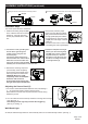
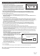

Adjusting the Sensor Head (C):
1. Aim sensor head toward desired detection area, maintaining a
5° - 40° downward angle to allow moisture to drain.
Note: Make sure sensor head is positioned with controls facing
toward the ground.
2. You can rotate the sensor head up and down to change the coverage
area. (See Fig. 1)
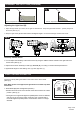
Note: Range set too high may increase false triggering.
(See Fig. 2 and Fig. 3)
Fig. 1
C
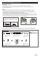
Wall Wash Light
Wall Wash Light:
At dusk,the wall wash light will be on automactically and turns off automactically at dawn. (See Fig. 1)
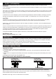
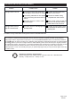
ASSEMBLY INSTRUCTIONS (continued)
5. With silicone caulking compound
(not included), caulk completely
around where the backplate of the
fixture (A) meets the wall surface.
CAUTION: Be sure to caulk
completely where the backplate
meets the wall surface to
prevent water from seeping into
the light fixture (A) and outlet box.
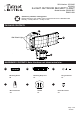
Controls
Backplate
For eave mounted only:
Swing the sensor head towards the mounting bracket.
Rotate the sensor head clockwise 180˚ so the controls face down.
Turn off the power at fuse or circuit box.
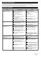
Installation Steps
1. Install the mounting strap unit (BB)
to the outlet box with the screw bolt
toward out, using two mounting
screws (AA) that best fit the outlet
box.
5
3. Connect the house grounding wire
and the fixture grounding wire
(yellow / green) using the wire
connector (DD).
Connect the fixture black wire to
the house black wire and the fixture
white wire to the house white wire
using wire connector (DD) provided.
Carefully tuck the wires back into the outlet box.
2. Remove the protective paper
barrier from the adhesive gasket
(EE), and thread the fixture wires
through gasket (EE),then adhere
the gasket (EE) to mounting strap
unit(BB) and outer edge of surface
outlet box.
Ensure that the screw on the mounting strap unit (BB)
is threading the hole of gasket (EE).
4. Attach the backplate of the light
fixture (A) to the mounting strap
unit (BB), then secure it with the
ring and screw (CC). Push the
decorative cover (FF) firmly into
the fixture mounting screw hole
on the light fixture (A).
A
Controls
Controls
1
AA
BB
Outlet Box
4
CC
FF
BB
A
Page 3 of 8
201029
3
DD
2
EE
BB