
Installation Instructions


Please read and understand this entire manual before attempting to assemble, operate or install the product.
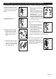
WARNING
● Turn off electricity at main fuse box (or circuit breaker box) before beginning installation by removing fuse (or
switching off circuit breaker).
● Be careful not to damage or cut the wire insulation (covering) during fixture installation. Do not permit wires to contact
any surface having a sharp edge. To do so may damage or cut the wire insulation, which could cause serious injury
or death from electric shock.
CAUTION
● All electrical connections must be in agreement with local codes, ordinances or the national electric code (NEC).
Contact your municipal building department to learn about your local codes, permits and/or inspections.
● Risk of fire – most dwellings built before 1985 have supply wire rated for 140°F/60ºC. Consult a qualified electrician
before installation.
● Do not connect this fixture to an electrical system that does not provide a means for equipment grounding. Never use
a fixture in a two-wire system that is not grounded. If you are not sure your lighting system has a grounding means,
do not attempt to install this fixture. Contact a qualified, licensed electrician for information with regards to proper
grounding methods as required by the local electrical code in your area.
Before beginning assembly, installation or operation of product, make sure all parts are present. Compare parts with
package contents list and diagram on previous page. If any part is missing or damaged, do not attempt to assemble,
install or operate the product. Contact customer service for replacement parts.
Tools Required for Assembly (not included): Screwdriver, Phillips Screwdriver, Pliers, Electrical Tape, Wire Cutters,
Safety Glasses, Ladder, Wire Stripper.
Page 2 of 5
SAFETY INFORMATION
Vintage Bulb Max.60W
(included)
2
Groove
Track (sold separately)
Socket Ring
Metal
Tab
Metal
Tab
Release
Lever
3. Install a Vintage Bulb Max.60W.
(included)
Turn on the power at fuse or circuit
box.
90˚
2. To attach the adapter(A) to the
track and align groove side (with
two internal copper strips) of the
track and the side with two metal
tabs of the adapter(A). Push top
portion of the adapter(A) into the
slot in the track and then turn 90˚.
To remove, depress the release
lever and turn 90˚.
Note:
1. The adapter can only be
assembled if the groove side
of the track and the side with
two metal tabs of the adapter are aligned.
2. If the track and the adapter are not aligned
properly, the light won't work.
B
FF
C
A
A
ASSEMBLY INSTRUCTIONS FOR TRACK MOUNTING
PREPARATION
Turn off the power at fuse or circuit box.
1. Attach the metal frame (C) to the
main fixture (B), and secure it with
the socket ring.
1 3