
Installation Instructions


Page 3 of 5
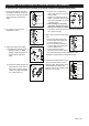
ASSEMBLY INSTRUCTIONS FOR TRACK MOUNTING (continued)
1
2
3a
3b
5
Set Screw
Adapter Cover
Adapter Holder
Slide Pad
Spring
1. Remove the adapter cover from
the adapter holder by loosening
the set screws. Remove the slide
pad and spring, and set them
aside.
Wire Nut
Adapter Cover
Adapter Holder
Cable
2. Unscrew the wire nuts and
separate the wires.
4
Wire Nut
Adapter Cover
Adapter Holder
Cable
3. Adjust the length of the cable:
a.) Measure the desired length of
cable and mark "A"; Slide
adapter holder down past "A".
Remove strain relief from
cable.
1"
A
A
Adapter
Holder
Strain Relief
Strain Relief
A
A
b.) Weave the cable through the
stain relief as shown. Pull on
both ends of cable to tighten,
making sure that strain relief
is 1" above mark "A".
Slide Pad
Spring
Adapter Holder
Adapter Cover
Set Screw
Cable
5. Pull down the cable until the strain
relief touches the bottom of the
adapter holder. Replace the spring
and slide pad, and fasten the
adapter cover to the adapter holder
with the 2 set screws.
To Shorten the Cable of the Pendant (If in doubt, consult a qualified electrician)
c.) Leave 2-3/4" of cable above
strain relief and then cut off the
excess cable.
Measure 2" down from end of
cable, cut carefully around cable
and peel off insulation to expose
3 internal wires
Note: Cutting too deep may
cut off the internal wires and
destroy the insulation surface of the internal wires.
Peel off the wires from the top about 3/8" to expose
the copper for wiring.
3c
3/8"
A
A
1"
Cut
2-3/4"
2"
4. Make wire connections using wire
nuts.
a.
Connect
the fixture black wire
from the cable to the black wire
from the adapter cover.
b.
Connect
the fixture white wire
from the cable to the white wire
from the adapter cover.
c.
Connect
the fixture green
grounding wire from the cable to
the green grounding wire from the adapter cover.
Carefully tuck wires back into the adapter holder.