
Installation Instructions
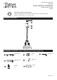

Please read and understand this entire manual before attempting to assemble, operate or install the product.
WARNING
● Turn off electricity at main fuse box (or circuit breaker box) before beginning installation by removing fuse (or
switching off circuit breaker).
● Be careful not to damage or cut the wire insulation (covering) during fixture installation. Do not permit wires to contact
any surface having a sharp edge. To do so may damage or cut the wire insulation, which could cause serious injury
or death from electric shock.
● LED electronics can be damaged by electro static discharge (ESD)shock. Before installation, discharge yourself
by touching a grounded bare metal surface to remove this hazard. To avoid damage, do not touch the LED module.
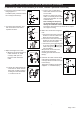
CAUTION
● All electrical connections must be in agreement with local codes, ordinances or the national electric code (NEC).
Contact your municipal building department to learn about your local codes, permits and/or inspections.
● Risk of fire – most dwellings built before 1985 have supply wire rated for 140°F/60ºC. Consult a qualified electrician
before installation.
● Do not connect this fixture to an electrical system that does not provide a means for equipment grounding. Never use
a fixture in a two-wire system that is not grounded. If you are not sure your lighting system has a grounding means,
do not attempt to install this fixture. Contact a qualified, licensed electrician for information with regards to proper
grounding methods as required by the local electrical code in your area.
● This fixture is dimmable with a forward phase electronic dimmer. Dimmers tested to be compatible with this
fixture are the Lutron: MSCL-OP153MH, MACL-153MH, DVWCL-153PH, TGCL-153PH, SCL-153PH.
If you are unfamiliar with electrical installation, it is recommended to use a qualified electrician for your installation(s).
Dimming range: 100% full illumination to 10% of full illumination.
Before beginning assembly, installation or operation of product, make sure all parts are present. Compare parts with
package contents list and diagram on previous page. If any part is missing or damaged, do not attempt to assemble,
install or operate the product. Contact customer service for replacement parts.
Tools Required for Assembly (not included): Screwdriver, Phillips Screwdriver, Pliers, Electrical Tape, Wire Cutters,
Safety Glasses, Ladder, Wire Stripper.
Page 2 of 5
SAFETY INFORMATION
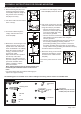
ASSEMBLY INSTRUCTIONS FOR TRACK MOUNTING
PREPARATION
Turn off the power at fuse or circuit box.
1. Loosen the upper headless
screw using supplied “ L ”
screwdriver(GG), and then
unscrews the cap(A) and
tube(C) from the rail
adapter(B) of spot light,
finally, turn up the movable
part of rail adapter(B).
1
B
A
C
Movable part
of Rail Adapter
2
B
A
B
C
Brass Clip
Ground Strip
Brass Strip
Rail
Ground Clip
2. Attach the rail adapter(B) onto
the rail (rail is sold separately).
Close back the movable
part of rail adapter(B) over
the rail, then restore the
cap(A) and tube(C) back to the
rail adapter(B), tighten the
headless screw using supplied
“ L ” screwdriver(GG). Make
certain that the brass clips of
the adapter(B) are connected
properly with the brass strips.
Note: To ensure the fixture
works correctly, make sure
the connection between the
adapter and the rail is
correct. The ground strip
on the rail is always facing
to the ceiling.
Turn on the power at fuse or
circuit box.
Rail
Movable part
of Rail Adapter
GG
GG
Headless
Screw
Headless
Screw