DVSCM-02 PATTERSON-KELLEY THERMIFIC® DIRECT VENT/SEALED COMBUSTION GAS-FIRED BOILER Supplement to the standard Installation and Owner's Manual (TBIG - Latest Edition) C.S.A Design-Certified Complies with ANSI Z21.13/CSA 4.9 Gas-Fired Low Pressure Steam and Hot Water Boilers ASME Code, Section IV Certified by Patterson-Kelley C.S.A Design-Certified Complies with ANSI Z21.13/CSA 4.9 Gas-Fired Low Pressure Steam and Hot Water Boilers Installation Date: _______________________ 100 Burson Street, P.O.
® Thermific Gas-Fired Boiler Table of Contents 1.0 INTRODUCTION..................................1 6.1c Lo-Hi-Lo IRI .................................... 17 6.1d On-Off Series 1500, 1700, 2000 ..... 19 6.1e On-Off IRI Series 1500, 1700, 2000 21 6.2 Auxiliary Control Panel...................... 23 6.2.1 On-Off Auxiliary Control Panel .... 23 1.1 Code Compliance................................1 1.1.1 Direct Vent/Sealed Combustion System ..............................................1 1.1.
® Thermific Gas-Fired Boiler Introduction 1.0 INTRODUCTION Direct vent (ANSI Z21.13) is a closed system method of ducting the combustion air directly from the outside of the building into the inlet compartment of the burner, and a sealed exhaust vent from the combustion chamber to the outdoors. The direct vent/sealed combustion option is available on the Thermific® boilers on Series 700, 1000, 1200, 1500, 1700, and 2000.
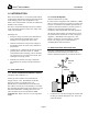
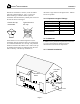
® Thermific Gas-Fired Boiler Introduction/Safety Sidewall Air Inlet Roof Exhaust Vent Exhaust Vent Sidewall Air Inlet 2. Both the combustion air inlet and flue gas exhaust through the sidewall. 4. The combustion air inlet from the roof and the flue gas exhaust through the sidewall. Air Inlet 1.3 PURPOSE AND SCOPE OF THIS MANUAL Exhaust Vent This manual is a supplement and companion to the Thermific Installation and Owner's Manual. "TBIG." Both documents must be used together.
® Thermific Gas-Fired Boiler Installation Do not manifold two (2) or more units into a common sidewall vent system without provisions for additional forced draft. 3.0 INSTALLATION 3.1 COMPONENTS PROVIDED The direct vent/sealed combustion option is shipped with the following items shipped loose for field installation: 3.2.2.2 PVC Duct Proper sealing of the tubing is necessary to prevent flow of combustion air from conditioned space.
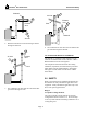
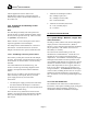
® Thermific Gas-Fired Boiler Installation Whichever material is used, the termination must point down and must be backed by a metal plate secured to the wall. Transition Duct Damper Round Important: The chosen inlet termination must be included in the calculation of the maximum allowable equivalent length. See Section 3.4.5 for equivalent lengths. Correct rain cap, unrestricted. Damper Housing Typical incorrect rain cap. (Sidewall installation shown.
® Thermific Gas-Fired Boiler Installation with the application of heat. Refer to the manufacturer's instructions. Wrap the joint with aluminum tape which is backed with an adhesive on the contact side. 1. Terminals for the damper actuator: DO = Damper Open (CW) DC = Damper Closed (CCW) DN = Neutral/Common 2. Terminals for the limit (end) switch 3.2.5 Inlet Damper and Auxiliary Control Panel (optional) SI = N.O.
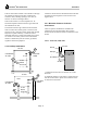
® Thermific Gas-Fired Boiler Installation 3.3.3 Exhaust Vent Connection at the Boiler from the outlet of the boot tee/ 135º tee to the inlet of the elbow. In addition, for sidewall venting, it is very important to provide a downward pitch of at least 1/4 inch per foot of run from the termination at the wall toward the boiler for proper drainage of the condensate and for buoyancy assist of the flue gas.
® Thermific Gas-Fired Boiler Installation Whichever termination is chosen, it must be double wall vent certified under UL 1738, or ULC-636. When installing a sidewall exhaust system the termination must be backed by a metal plate secured to the wall as shown in the figure. Correct rain cap, unrestricted. unrestrictive type similar to the figure above. Elbows are also acceptable. 3.4.
® Thermific Gas-Fired Boiler Installation If the air inlet and/or exhaust vent terminal are through the sidewall, clearances from other exhaust/inlet, windows, doors, building openings, snow line, etc must be as shown in the figure above. There must be either 5' vertical separation or 10' horizontal separation between the flue gas outlet and the combustion air inlet. Clearances which must be maintained when both inlet and exhaust are through the roof are shown in the figures above. 3.4.
® Thermific Gas-Fired Boiler Installation/Operation normally closed contacts on the time delay relay and energizes the coil on the relay in the Auxiliary Control Panel. The relay will in turn energize the damper actuator to open the damper. When the damper is in the full open position, the limit switch will close and supply power to the contactor for the blower motor. 3.4.3.
® Thermific Gas-Fired Boiler Operation/Maintenance 4.2.1 Combustion Air Requirement, SCFM When the chart is completed, set up your boiler's combustion to the corresponding information at the temperature relative during the time of the start up. Enter your 100º F operational range. % Oxygen 8 7.9 7.8 7.7 7.6 7.5 7.4 7.3 7.2 7.1 7.0 6.9 6.8 6.7 6.6 6.5 6.4 6.3 6.2 6.1 6 % Carbon Dioxide 7.2 7.3 7.4 7.4 7.5 7.5 7.6 7.6 7.7 7.7 7.8 7.8 7.9 8 8 8.1 8.1 8.2 8.2 8.3 8.
® Thermific Gas-Fired Boiler Wiring Diagrams 6.0 WIRING DIAGRAMS 6.
® Thermific Gas-Fired Boiler Wiring Diagrams 6.
® Thermific Gas-Fired Boiler Wiring Diagrams 6.
® Thermific Gas-Fired Boiler Wiring Diagrams 6.
® Thermific Gas-Fired Boiler Wiring Diagrams 6.
® Thermific Gas-Fired Boiler Wiring Diagrams 6.
® Thermific Gas-Fired Boiler Wiring Diagrams 6.
® Thermific Gas-Fired Boiler Wiring Diagrams 6.
® Thermific Gas-Fired Boiler Wiring Diagrams 6.
® Thermific Gas-Fired Boiler Wiring Diagrams 6.
® Thermific Gas-Fired Boiler Wiring Diagrams 6.
® Thermific Gas-Fired Boiler Wiring Diagrams 6.
® Thermific Gas-Fired Boiler Wiring Diagrams 6.2 AUXILIARY CONTROL PANEL 6.2.
Page 24