MACH-05 PATTERSON-KELLEY MACH SERIES BOILER GAS-FIRED BOILER C.S.A Design-Certified Complies with ANSI Z21.13/CSA 4.9 Gas-Fired Low Pressure Steam and Hot Water Boilers ASME Code, Section IV Certified by Patterson-Kelley C.S.A Design-Certified Complies with ANSI Z21.13/CSA 4.9 Gas-Fired Low Pressure Steam and Hot Water Boilers Installation Date: _______________________ 100 Burson Street, P.O. Box 458, East Stroudsburg, PA 18301 Telephone: (877) 728-5351, Facsimile: (570) 476-7247 www.pkboilers.
MACH® Series Gas-Fired Boiler
MACH® Series Gas-Fired Boiler Table of Contents 1.0 INTRODUCTION ........................................1 3.6.11 Intake Duct Connection to Boiler ......... 12 2.0 SAFETY......................................................1 3.6.12 Intake Duct Terminations ..................... 12 2.1 General ..............................................................1 3.6.13 Vent Elbows ......................................... 13 2.2 Training..............................................................1 3.
MACH® Series Gas-Fired Boiler Table of Contents 5.1.3 Monthly (During Operation)....................30 6.1.3 Wiring Series C-450............................... 40 5.1.4 Semi-Annually (every 6 months)............31 6.1.4 Wiring Series C-750/900/1050............... 41 5.1.5 Annually .................................................31 6.2 Boiler Parts List ............................................... 42 5.2 Cleaning the Burner.........................................31 6.2.1 Main Assembly..........
MACH® Series Gas-Fired Boiler Safety 1.0 INTRODUCTION The P-K MACH® Series Gas-Fired Boilers are fully modulating using a variable speed combustion blower, sophisticated microprocessor controls, modulating gas safety shut off / control valves and a unique aluminum alloy heat exchanger capable of operating in a fully condensing mode to provide maximum efficiency in a minimum amount of space.
MACH® Series Gas-Fired Boiler Safety 2.5.2 Burn, Fire, and Explosion Hazards 2.4 SAFETY LABELS NOTE When opening leak test valves, always follow instructions in operation and safety manual. c 1998 HCS, Inc. 800-748-0241 Reorder No. 8032-01NHPK General Warning ! Hot Surface WARNING ! Improper use may result in fire or injury. Read instructions/safety manual before installing, operating or servicing boiler. c 1998 HCS, Inc.
MACH® Series Gas-Fired Boiler Safety • Burn hazard! Hot fluids. Use caution when servicing or draining boiler. • Fire and explosion hazards! Use caution when servicing burner. Propane (LPG) is heavier than air and may linger in the combustion chamber, vent lines, or elsewhere. • Gas leak hazard! Make sure the burner is installed correctly and burner hood is securely fastened following any maintenance performed on them. These connections cannot be tested after the burner is assembled.
MACH® Series Gas-Fired Boiler Safety 2.5.6 Slip, Fall Hazards 2.5.5 Pressure Hazards ! WARNING ! WARNING Improper use may result in fire or injury. Improper use may result in fire or injury. Read instructions/safety manual before installing, operating or servicing boiler. Read instructions/safety manual before installing, operating or servicing boiler. c 1998 HCS, Inc. 800-748-0241 c 1998 HCS, Inc. 800-748-0241 • Pressure hazard! Hot fluids.
MACH® Series Gas-Fired Boiler Installation 3.0 INSTALLATION Code, Section IV for 50 psig maximum operating pressure and/or 200º F maximum temperature. 3.1 RECEIVING AND STORAGE Other codes or approvals which apply will be labeled on the boiler. 3.1.1 Initial Inspection Upon receiving the boiler, inspect it for signs of shipping damage. Since some damage may be hidden, we recommend unpacking the boiler and removing the top cover and inspecting the boiler.
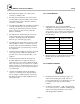
MACH® Series Gas-Fired Boiler Installation clearance and prevent distortion of the cabinet, (twisting, etc.) in addition to leveling. D D Adjustable Leg Bolts Minimum Clearances from Adjacent Walls, Ceiling, and Obstructions Type of Surface Adjustable Legs for Leveling and Floor Clearance 3.3.3 Clearances If the boiler is to be installed near combustible surfaces, the minimum clearances shown in the table below must be maintained.
MACH® Series Gas-Fired Boiler Installation An external electrical disconnect (not supplied with the boiler) with adequate overload protection is required. The boiler must be grounded in accordance with local codes or in the absence of such requirements, in the U.S. with National Electrical Codes, ANSI/NFPA No. 70 latest edition and in Canada to the current Canadian Electrical Code, Part I, CSA C22.1. Note: A dedicated earth ground (green wire) is required to avoid nuisance shutdowns.
MACH® Series Gas-Fired Boiler Installation If air is taken from another interior space, each opening should have a net free area of 1 square inch for each 1,000 Btu per hour of boiler input (450 square inches for a 450,000 Btu per hour.) 3.6 FLUE VENTING This boiler requires a special vent system. This boiler is not certified for use with Type "B" vent. This boiler is Category IV (condensing – positive pressure) as it is defined in ANSI Z21.13/CSA 4.9, latest edition.
MACH® Series Gas-Fired Boiler Installation 3.6.4 Vent Terminations WARNING! Do not locate intake or exhaust terminations directly above a walkway; dripping of condensation can cause icing of the walking surface. No rain cap required, or Tee. Mechanical draft vent terminal Direct vent terminal clearance minimum 12 in. Outside Plate Less than 10 ft. Cover Plate Fastener Sealant 4 ft. min. 4 ft. min. 3 ft min. 12 in. min Mechanical draft vent terminal Centering Support Plate 12 in. min.
MACH® Series Gas-Fired Boiler Installation 3.6.6 Sealed Combustion Air/Venting System The MACH Series Boilers are also certified for operation with a sealed combustion air and pressurized venting system. Such a system employs a sealed combustion air intake duct leading from outdoors and a sealed exhaust vent terminating outdoors. Air flow through the system is maintained by the fan inside the boiler assembly.
MACH® Series Gas-Fired Boiler Installation Exhaust Vent (Type of flue termination optional when roof venting.) Exhaust Vent (type of flue termination optional when roof venting.) Air Inlet (tee mounted horizontally.) Roof Air Inlet (Type of flue termination optional.) Roof Sidewall Sidewall Inlet, Roof Vent Roof Inlet and Vent Air Inlet (Type of flue termination optional.) Exhaust Vent (Sidewall venting requires vertical tee termination.
MACH® Series Gas-Fired Boiler Installation Exhaust Vent (Sidewall Venting Requires Up Elbow Mounted) 3.6.12 Intake Duct Terminations Roof Round Air inlet (Down Elbow Mounted) 90° Elbow Sidewall C750/900/1050 Sidewall Inlet and Vent 3.6.9 Intake Duct Materials and Sizes: Material: PVC, CPVC (Schedule 40), single wall galvanized steel, or other suitable materials. Sidewall Air Inlet (tee mounted horizontally) The intake duct must be sized for a maximum pressure drop of 0.22 inches W.C.
MACH® Series Gas-Fired Boiler Installation WARNING! Outside Plate Cover Plate Fastener Sealant Centering Support Plate Sealant Field Provided Inlet Screens All threaded connections must be made using a pipe compound that is resistant to the action of liquefied petroleum gases. Do not use Teflon tape on gas line threads. Remote Gas Shutoff (not supplied) Recommended Termination Natural Gas Supply By Installer 12" min. Union Intake Termination Details Drip Leg 3.6.
MACH® Series Gas-Fired Boiler Installation Pipe Capacity for Natural Gas Nominal Equivalent Pipe Length Iron Pipe Internal Size Diameter (Inches) (Inches) Maximum Capacity in Cubic Feet of Natural Gas per Hour Pressure Drop of 0.5 inch Water Column/Equivalent Length of Pipe (in feet) 90º Ell Tee (Feet) (Feet) 20 40 60 80 100 150 200 1/2 0.622 1.55 3.1 120 82 66 57 50 40 35 3/4 0.824 2.06 4.12 250 170 138 118 103 84 72 1 1.049 2.62 5.
MACH® Series Gas-Fired Boiler Installation 3.8.2 Boiler Inlet and Outlet Connections C750 C900 C1050 C450 C300 Proper flow rates may be achieved through a combination of primary and secondary flow loops. Multiple zones and pumps may result in different flow rates at different times. Consideration must be given to all possible conditions and their consequences.
MACH® Series Gas-Fired Boiler Installation Drain Valve and Piping 3.8.3 Boiler Water Piping by Installer Strainer To avoid possible contamination of the boiler with dirt, rust or sediment from the system, a strainer near the boiler inlet is strongly recommended. Even new systems may contain sufficient foreign material to eventually reduce the performance of the heat exchanger. Adequate circulation of good clean water is essential to maximum efficiency and long life of the boiler.
MACH® Series Gas-Fired Boiler Installation untreated make-up water will cause premature failure due to buildup of scale; such failure is not covered by warranty. IMPORTANT! Water pH If the piping system attached to this unit will be chemically cleaned, the boiler must be disconnected from the system and a bypass installed so that the chemical cleaning solution does not circulate through the boiler.
MACH® Series Gas-Fired Boiler Installation 3.10 PRE-START CHECK LIST WARNING! Before attempting to start the boiler, make sure the following items have been completed. After checking controls by manual adjustment, make sure they are always reset to their proper settings. 1. Section 3.9.1 Inspection. 2. Flue gas from the boiler is properly vented; (refer to Section 3.6) 3. Gas connection has been made, pressure tested for leakage, and the line purged of air.
MACH® Series Gas-Fired Boiler Installation 3. Smoothly close the downstream manual isolation valve to reduce the gas flow and cause flame failure. 4 The display will flash E-02 indicating a flame failure. The E-02 lockout will remain until reset on the display. After completing this test, turn off the boiler and open the downstream manual isolation valve. 3.11.2 Test of Low Water Cut-out The boiler is furnished with a probe-type low water cut-out in the outlet nozzle.
MACH® Series Gas-Fired Boiler Installation 3.12 INITIAL ADJUSTMENTS 3.12.1 Operating Temperature Controller Mode Description Display Example Standby (Stby) Normal display mode 1st digit without a dot 0 180 Parameter (PArA) Parameter settings 1st digit with a dot 1.125 Information (InFo) display boiler sensors 1st digit with a blinking dot* 1.180* Standby Mode: The display defaults to this mode at startup or reset of the control.
MACH® Series Gas-Fired Boiler First Digit Installation Information Mode: Boiler Status delay. No system call for heat. 8 Burner off - Domestic Hot Water pump running on delay. No system call for heat. 9 and b flashing Burner off – auto reset lockout. A code is displayed indicating the reason for the lockout. (See Troubleshooting Section 5.5.
MACH® Series Gas-Fired Boiler Installation Internal Setpoint: Item The internal setpoint is set with parameter 4. The boiler temperature control modulates the boiler to maintain this internal setpoint. The upper and lower temperature differentials are used to instruct the boiler at what temperature to turn on and at what temperature to turn off. Item Parameter Value Allowable Range Setpoint 4 160 68-185 Low Temp. Differential 22 10 0-36 High Temp. Differential 23 9 0-36 Low Temp.
MACH® Series Gas-Fired Boiler Installation The control automatically detects the presence of the outdoor air sensor. If an outdoor air sensor is present, the boiler automatically defaults to outdoor air reset for setting boiler temp. The parameters should be set according to the following table: Item Parameter Value °F Allowable Range °F Maximum Setpoint 4 180 68-185 Minimum Setpoint 5 80 60-140 Outdoor Air Minimum Temp. 6 20 4-50 Outdoor Air Maximum Temp.
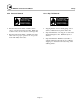
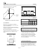
MACH® Series Gas-Fired Boiler Installation Analog Input to Control Firing Rate: Analog Input to Adjust Setpoint: Analog Input S etpoint Analog Input Firing Rate 100 200 90 70 B oiler Setpoint Non adjustable C urve 100 F iring R ate B oiler Setpoint 80 150 60 50 40 30 20 50 10 0 0 0 0 1 2 3 4 5 6 7 8 9 1 2 3 4 5 6 7 8 9 10 10 V oltag e V oltage The control must be configured for analog input direct drive by setting parameter 34 to 02.
MACH® Series Gas-Fired Boiler Installation This port is located on the upstream side of the valve body for measuring supply pressure. (See figure below.) Boiler Test Mode: The test mode should be used when checking and setting the gas safety shut off / control valves on the MACH Series boilers.
MACH® Series Gas-Fired Boiler Installation Table 3-1 Combustion Reading For Setting Gas Safety Shut Off / Control Valves Nominal High Fire Setting Low Fire Setting Fuel Gas Pressure % O2 % CO2 % O2 % CO2 Natural Gas 7" W.C 5.0 + 0.2 9.0 + 0.2 5.2 + 0.2 8.8 + 0.2 Propane 11" W.C 5.0 + 0.2 10.4 + 0.3 5.2 + 0.2 10.3 + 0.3 Adjustment: There must be sufficient load to operate the boiler at high fire to perform the following adjustments.
MACH® Series Gas-Fired Boiler Installation Low Fire Setting MACH C750, C900 & C450 Required Tools: Set boiler to the “Test Mode Low”, as described above, to achieve minimum firing rate of the boiler. Check combustion readings using a combustion analyzer.
MACH® Series Gas-Fired Boiler Operation 4.0 OPERATION 4.2.1 Lighting Procedures 4.1 GENERAL 1. Close main gas valve. 2. Turn On-Off switch to "OFF" position. 4.1.1 Control Panel Front 3. Wait 5 minutes. 4. Open main gas valve. 5. Turn On-Off switch to "ON" position. 6. Push reset button on display panel if required. 7. Push reset on low gas pressure switch and high gas pressure switch. The controller will now complete the automatic firing sequence.
MACH® Series Gas-Fired Boiler Operation 4.2.3 Emergency Shut-Off The main gas cock should be closed immediately if an emergency situation occurs. Main Gas Cock WARNING! If overheating occurs or the gas supply fails to shut off, do not turn off or disconnect the electrical supply to the pump. Instead, shut off the gas supply at a location external to the boiler. Emergency Shut-Off 4.3 TYPICAL BOILER OPERATING CONDITIONS Model Number Input Rating (Btu/hr) Natural Gas LP Gas Total *(1030 Btu/cu.
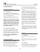
MACH® Series Gas-Fired Boiler Maintenance 5.0 MAINTENANCE WARNING! Check daily to be sure that the boiler area is free and clear of any combustible materials, including flammable vapors and liquids. 5.1 MAINTENANCE AND INSPECTION SCHEDULE WARNING! 5.1.2 Weekly Label all wires prior to disconnection when servicing controls. Wiring errors can cause improper and dangerous operation. Observe the conditions of the main flame. A normal high fire flame is blue.
MACH® Series Gas-Fired Boiler Maintenance 5.1.4 Semi-Annually (every 6 months) 7. Qualified service personnel should thoroughly inspect the heating system and correct any problems prior to re-starting the boiler. In addition to the recommended monthly service: 1. Clean burner of any accumulated dust or lint. See Section 5.2 on "Cleaning the Burner." 2. Inspect burner for any signs of deterioration or corrosion. Replace immediately if deterioration or corrosion is evident.
MACH® Series Gas-Fired Boiler Maintenance 5.4 SEQUENCE OF OPERATION 1. When the On/Off (Main power) switch is turned on, power is provided through a circuit breaker to the boiler control and the combustion blower. The boiler control powers a 24 V transformer. The boiler control supplies 24 V power through a high limit temperature switch and a low water level control. 2. The low water level control is closed when there is water in the boiler up to the probe. 3.
MACH® Series Gas-Fired Boiler Maintenance Loss of Water Level The low water switch opens when there is insufficient water level in the boiler. E 12 is shown on the display, and burner operation is interrupted. When the correct water level is re-established, pushing the reset button will return the sequence to Step 5, provided that the other limits are satisfied.
MACH® Series Gas-Fired Boiler Maintenance 5.5.1 Manual Reset Service Codes Code Lockout Description E 00 False flame. A flame signal is present when it shouldn’t be. E 02 Flame failure. The burner did not light on startup, or loss of flame during run. E 03 Gas Valve error. Check all gas valves electrical connections. E 04 General lockout. The power was lost after a lockout. The control loses the description of the lockout on power loss. E 05 Internal control failure. Call for service.
MACH® Series Gas-Fired Boiler Maintenance 5.5.2 Auto-reset Service Codes Code Lockout Description b 08 Air pressure switch open. The air pressure switch failed to close to indicate sufficient air flow to start the boiler. b 18 Outlet high limit temp. The outlet water temperature has exceeded the internal high limit temperature setting. b 19 Return high limit temp. The return water temperature has exceeded the internal high limit temperature setting. b 24 Switched inlet / outlet.
MACH® Series Gas-Fired Boiler Parts and Technical Support 6.0 PARTS/TECHNICAL SUPPORT Spare parts and replacement parts can be ordered from Patterson-Kelley by calling toll free (877) 728-5351. Ask for the Heat Transfer Department. The fax number is (570) 476-7247. Refer to the parts list shown on the assembly drawing provided with this manual. Technical information is also available at the above number.
MACH® Series Gas-Fired Boiler Parts and Technical Support 6.1 WIRING DIAGRAMS 6.1.1 Terminal Block Assignments – High Voltage Circuit (TB2) Terminal Number Label Description 1 115 VAC LINE Boiler Supply Power, 115 VAC, 60 HZ, 1 ph, 8 amp 2 115 VAC NEUTRAL 3 115 VAC NEUTRAL Aux. Switched Output 4 115 VAC NEUTRAL Boiler Circ. Pump 5 115 VAC NEUTRAL DHW Circ. Pump 6 GROUND Boiler Supply Ground 7 GROUND Aux .Ground 8 GROUND 9 115 VAC SW. OUTPUT Aux.
MACH® Series Gas-Fired Boiler Parts and Technical Support 6.1.1a Terminal Block Assignments – Low Voltage Circuit (TB1) Terminal Number Label Description 1 HEAT REQUEST 2 HEAT REQUEST 3 INTERLOCK JUMPER 4 INTERLOCK JUMPER 5 DHW TEMP. SENSOR 6 OUTDOOR TEMP SENSOR Thermistor - factory option. 7 CIRC. PMP PWM SIGNAL Pulse Width Modulation. 8 COMMON Common to be used with 5, 6, 7, and 10 when used. 9 COMMON Common to be used with 5, 6, 7, and 10 when used. 10 O-10 V ANAL.
MACH® Series Gas-Fired Boiler Parts and Technical Support 6.1.
MACH® Series Gas-Fired Boiler Parts and Technical Support 6.1.
MACH® Series Gas-Fired Boiler Parts and Technical Support 6.1.
MACH® Series Gas-Fired Boiler Parts and Technical Support 6.2 BOILER PARTS LIST 6.2.
MACH® Series Gas-Fired Boiler Parts and Technical Support 6.2.
MACH® Series Gas-Fired Boiler Parts and Technical Support 6.2.
MACH® Series Gas-Fired Boiler Parts and Technical Support 6.2.
MACH® Series Gas-Fired Boiler Parts and Technical Support 6.2.
MACH® Series Gas-Fired Boiler Parts and Technical Support 6.2.
MACH® Series Gas-Fired Boiler Parts and Technical Support 6.2.
MACH® Series Gas-Fired Boiler Parts and Technical Support 6.2.
MACH® Series Gas-Fired Boiler Limited Warranty 7.0 LIMITED WARRANTY Subject to the terms and conditions herein and except as provided below with respect to products or parts not manufactured by Patterson-Kelley Co., Seller warrants to the original owner at the original installation site that products manufactured by Seller ("Products") will be free from defects in materials and workmanship for a period of five (5) years from date of shipment (the "Warranty Period").
MACH® Series Gas-Fired Boiler Limited Warranty SEVERABILITY charges to return the boiler and or components. Seller's liability under this warranty shall not in any case exceed the amount paid for the Product found to be defective. To the extent that any provision of this warranty would be void or prohibited under applicable law, such provisions shall be limited in effect to the minimum extent necessary to render the remaining provisions hereof enforceable.
MACH® Series Gas-Fired Boiler Appendix 8.
Outdoor Air Offset Maximum fanspeed CH (hundreds) Maximum fanspeed CH (units) Maximum fanspeed DHW (hundreds) Maximum fanspeed DHW (units) Minimum fanspeed (hundreds) Minimum fanspeed (units) Ignition fanspeed (hundreds) Postpumptime CH Postpumptime DHW CH modulation hysteresis On CH modulation hysteresis Off DHW modulation hysteresis On DHW modulation hysteresis Off DHW detection hysteresis On 12 13 14 15 16 17 18 19 20 21 22 23 24 25 26 11 Booster time 4 Setpoint or Maximum Setpoint (OAR) Service Set
Difference T1-T2 for modulating back RMCI address Setvalue addition for DHW, Parameter 1 CH Heat Request Type (1st digit) 2nd CH-circuit 31 32 33 34 DHW: 3 Way Valve or Pump (1st digit) 35 DHW Type (2nd digit) (2nd digit) CH Heat Request Type 54 F 30 x 10.2 seconds 30 x 10.2 seconds -36 F 0 seconds 0 seconds 0 = switch with burner On 1 x 10.2 seconds 9F -1 = RMCI Off 0F DHW detection hysteresis Off Restart delay CH x 10.2 seconds Restart delay DHW x 10.
39 40 41 42 Special pump CH / DHW Max Setpoint, 2nd CH-circuit Min Setpoint, 2nd CH-circuit Hysteresis 2nd CH-circuit Low/off Cycle 36 Manual fanspeed 37 PWM-level CH-pump: 38 Hold boiler water DHW only No.