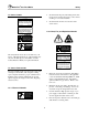
MOD-04 PATTERSON-KELLEY THERMIFIC® MODU-FIRE® GAS-FIRED BOILER Installation and Owner's Manual C.S.A Design-Certified Complies with ANSI Z21.13/CSA 4.9 Gas-Fired Low Pressure Steam and Hot Water Boilers ASME Code, Section IV Certified by Patterson-Kelley C.S.A Design-Certified Complies with ANSI Z21.13/CSA 4.9 Gas-Fired Low Pressure Steam and Hot Water Boilers Installation Date: _______________________ 100 Burson Street, P.O.
Modu-Fire® Gas-Fired Boiler Table of Contents 1.0 INTRODUCTION ........................................1 3.8.1 Piping Design ......................................11 2.0 SAFETY......................................................1 3.8.2 Boiler Inlet and Outlet Connections ....12 2.1 General ....................................................... 1 3.8.3 Boiler Water Piping by Installer...........12 2.2 Training ....................................................... 1 3.8.4 Flushing and Filling ..
Modu-Fire® Gas-Fired Boiler Table of Contents 5.3 Removing the Exchanger ......................... 26 IRI Unit - Local Control - Logic Diagram .......36 5.4 After All Repairs or Maintenance .............. 26 IRI Unit - Remote Control - Logic Diagram ...37 5.5 Sequence of Operation.............................. 27 IRI Unit - Local & Remote Control - Logic Diagram ..................................................38 5.5.1 Standard Modulating ..........................
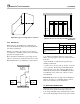
Modu-Fire® Gas-Fired Boiler Introduction/Safety 1.0 INTRODUCTION The P-K MODU-FIRE® Gas Fired Boiler is a revolutionary advance; Patterson-Kelley now combines full-modulation burner control with our time-tested modular hot water boiler design. The result is “modular full-modulation”- Modu-Fire! This new hybrid boiler combines the best of our earlier designs with a new generation of burner and control technology.
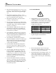
Modu-Fire® Gas-Fired Boiler Safety 2.4 SAFETY LABELS • Shock hazard! Properly lockout/tagout the electrical service and all other energy sources before working on or near the machine. • Shock hazard! Boiler is not rated for washdown service. NOTE Make sure this union is tight before closing cabinet cover after servicing boiler. c 1998 HCS, Inc. 800-748-0241 Reorder No. 8032-02NHAK NOTE When opening leak test valves, always follow instructions in operation and safety manual. c 1998 HCS, Inc.
Modu-Fire® Gas-Fired Boiler • Fire and explosion hazards! Do not store or use gasoline or other flammable vapors or liquids in the vicinity of this or any other gas fired appliance. • Burn hazard! Possible hot surfaces. Do not touch gas vent during firing operation. Use only factory recommended vent components. • Burn hazard! Hot fluids. Use caution when servicing or draining boiler. • Fire and explosion hazards! Use caution when servicing burner.
Modu-Fire® Gas-Fired Boiler Safety 2.5.6 Slip, Fall Hazards 2.5.5 Pressure Hazards ! WARNING ! Improper use may result in fire or injury. Read instructions/safety manual before installing, operating or servicing boiler. Read instructions/safety manual before installing, operating or servicing boiler. c 1998 HCS, Inc. 800-748-0241 • • WARNING Improper use may result in fire or injury. c 1998 HCS, Inc. 800-748-0241 Pressure hazard! Hot fluids.
Modu-Fire® Gas-Fired Boiler Installation temperature. Other codes or approvals which apply will be labeled on the boiler. 3.0 INSTALLATION Installation of the boiler must conform to all the requirements of all national, state and local codes established by the authorities having jurisdiction or, in the absence of such requirements, in the U.S. to the National Fuel Gas Code, ANSI Z223.1/NFPA 54, latest edition.
Modu-Fire® Gas-Fired Boiler Installation D Adjustable Legs for Leveling and Floor Clearance D Minimum Clearances from Adjacent Walls, Ceiling, and Obstructions 3.3.3 Clearances Type of Surface If the boiler is to be installed near combustible surfaces, the minimum clearances shown in the table below must be maintained. Failure to provide for the service access clearances, even with non-combustible surfaces, may cause future problems servicing the boiler.
Modu-Fire® Gas-Fired Boiler Installation If air is taken directly from outside the building, each opening should have a net free area of 1 square inch for each 4,000 Btu per hour of total boiler input. For instance, 300 square inches (2-1/12 square feet) are required for 1,200,000 Btu per hour input. is wired for 120 volts, single phase, 60 hertz. The total operating amperage is indicated on the rating nameplate. The 1000 series require less than 9 amps; the 1500 and 2000 series less than 12 amps.
Modu-Fire® Gas-Fired Boiler Installation tee. The condensate drain must be routed to a sewer drain trap or pump in accordance with local codes. Refer to diagram under Vent Elbows. WARNING! This boiler should not be installed with an automatic damper on the flue. Damper failure could create an explosion hazard. 3.6.2 Barometric Damper In Canada, the boiler is certified for installation with a “Power Venter” by the Canadian Gas Association when installed with the “listed accessories.
Modu-Fire® Gas-Fired Boiler Installation 4. Place the appliance being inspected in operation. Follow the lighting instructions. Adjust the thermostat so that the appliance will operate continuously. Correct Listed Termination 5. Test for spillage at the draft hood relief opening after 5 minutes of main burner operation. Use the flame of a match or candle or smoke from a cigarette, cigar or pipe. Incorrect Termination (too restrictive) 6.
Modu-Fire® Gas-Fired Boiler Installation on the boiler. Gas piping should be installed in accordance with National Fuel Gas Code, ANSI Z223.1, latest edition, and any other local codes which may apply; in Canada see CAN/CGA-B 149. By Installer Remote Gas Shutoff (not supplied) Note: See chart below for required pipe size, based on overall length of pipe from meter plus equivalent length of all fittings. Approximate sizing may be based on 1 cubic foot of natural gas per 1,000 Btu per hour input, i.e.
Modu-Fire® Gas-Fired Boiler Installation 3.7.1 Gas Supply Piping by Installer in accordance with the National Fuel Gas Code (NFPA 54), ANSI Z223.1, which states: The boiler and all gas piping connections should be pressure-tested and must be checked for leaks before being placed into service. Test with compressed air or inert gas if possible.
Modu-Fire® Gas-Fired Boiler Installation Consideration must be given to all possible conditions and their consequences. Note: Pipe unions and isolating valves must be installed in both water connections for ease of service. Piping With Refrigeration Machines The bottom connection to the boiler is the INLET and must be used for the return from the system. When used with a refrigeration system, the boiler shall be installed so that chilled medium is piped in parallel with the boiler.
Modu-Fire® Gas-Fired Boiler Installation treated make-up water can cause premature failure due to buildup of scale. Such failure is not covered by warranty. WARNING! Never install a valve that can isolate the low water cutoff from the boiler. Scale can also reduce efficiency. For example, a scale thickness of 1/16" will result in a 12.5% loss of efficiency. Drain Valve and Piping The boiler is not provided with external drain connections.
Modu-Fire® Gas-Fired Boiler Installation 2. With the main gas cock (inlet manual gas valve) open and the pilot gas cock open, the burner should be cycled on. After all the safety limits on gas pressure, water flow and temperature are satisfied, the blower will run and pre-purge the boiler. 2. Gas connection has been made, pressure tested for leakage, and the line purged of air. Make sure all required bleeds and vents have been installed. 3.
Modu-Fire® Gas-Fired Boiler Installation 3.12 INITIAL ADJUSTMENTS the main burner shuts off (the green "Heat" indicator will go out). The high-limit switch must be manually reset after testing. This same check should also be made for the "Operating Temperature" control. After completion of these tests, readjust thermostats to desired operating temperature and set high-limit temperature, typically 20º F above operating temperature. 3.12.
Modu-Fire® Gas-Fired Boiler Installation For example, assume the following settings: Item Display Value Setpoint 1 SP1 160 Low Temp Differential HyS1 -5 High Temp Differential HyS3 12 Low Temp Setpoint SPL 150 High Temp Setpoint SPH 195 The boiler will modulate to try to maintain 160 o F. If the temperature increases to 172 o F which is Setpoint 1 (SP1) 160 + High Temp Differential (HyS3) 12, it will shut off.
Modu-Fire® Gas-Fired Boiler Installation Analog Input Direct Drive PARAMETER level, and the The firing rate of the boiler is controlled by an external analog signal, usually from a multiple boiler control. The boiler turns on and off as directed by the external control. CONFIGURATION level. The following table indicates the menu options available from each level. The options available depend on the operating mode of the boiler.
Modu-Fire® Gas-Fired Boiler Installation To change to manual operation press EXIT for 5 seconds. during manual operation, then the control is changed to automatic operation. The LED above the hand symbol lights up. Change the firing rate of the boiler with . Parameter Level or The firing rate increases as long as is pressed. The firing rate decreases as long as pressed. is To access the parameter level press and hold the PGM button for longer than two (2) seconds.
Modu-Fire® Gas-Fired Boiler Installation Table 1 - Table of Parameters 19
Modu-Fire® Gas-Fired Boiler Installation Configuration Level 3.12.2 Air Flow Adjustments The configuration level is used to set up the control for the sensors used, and the functioning of the alarm relay. The configuration level must be adjusted by factory-trained personnel only. The air flow is pre-set at the factory prior to shipment. The air (and gas) may have to be adjusted for local conditions. All air flow adjustments must be performed by factory-trained personnel. 3.12.
Modu-Fire® Gas-Fired Boiler Installation 3.12.3 Gas Pressure Adjustment See rating plate for the minimum and maximum gas pressure of the boiler. Each boiler is furnished with two plugged taps in the gas manifold for test gauge connections. One tap is located at the main gas cock for measuring the gas supply pressure (1/4” IPS). The supply pressure during main burner operation must be greater than the minimum indicated on the rating plate.
Modu-Fire® Gas-Fired Boiler Operation 4.0 OPERATION Cabinet Air Pressure Test 4.1 GENERAL 4.1.1 Control Panel Front Temperature Control Pilot Gas Pressure Test Main Gas Pressure Test Operating Instructions High Gas Pressure Switch Low Gas Pressure Switch Pilot Gas Cock Indicator Lights On-Off Switch Main Gas Cock The front of the control panel shows Operating Instructions and a series of illuminated indicator lights which show the condition of the boiler. 4.
Modu-Fire® Gas-Fired Boiler Operation ply to the pump. Instead, shut off the gas supply at a location external to the boiler. 4. Turn power switch on. If a red warning indicator is illuminated, see call for factory-trained personnel to troubleshoot the problem and implement corrective action. Wait five minutes before attempting to reset boiler. 4.3 TYPICAL BOILER OPERATING CONDITIONS 4.2.2 Normal Shut Down Procedures 1. Close all manual gas valves. 2. Turn off electric power. Natural Gas (1030 Btu/cu.
Modu-Fire® Gas-Fired Boiler Maintenance 5.0 MAINTENANCE 5.1.2 Weekly General Lock out / Tag out procedure must be employed when servicing unit. Observe the conditions of the pilot and main flame. A normal High fire flame is blue. If the flame is yellow, then corrective action must be taken. In Low fire the burner will glow a yellowish orange. Hazard analysis should be performed by end user to insure safety of their employees and/or service technicians.
Modu-Fire® Gas-Fired Boiler Maintenance 5.2 CLEANING THE BURNER 3. Inspect burner for any signs of deterioration or corrosion. Replace immediately if deterioration or corrosion is evident. Ignition Electrode The blower motor is permanently lubricated and does not require periodic lubrication. Mixer Core This work should be performed by factory-trained personnel. UV Scanner 5.1.5 Annually In addition to the recommended monthly service: Burner Tube 1.
Modu-Fire® Gas-Fired Boiler Maintenance 8. Remove the nuts and bolts from the flanges of the inlet and outlet nozzles at the rear of the outer casing. 9. Remove the exchanger and clean the fins. Note: The inner and outer cabinets are separate parts and reassembly is easier if the inner cabinet and exchanger are removed together as one unit. Pilot Tube WARNING! Ceramic Spider The heat exchanger is heavy; use proper lifting equipment and techniques. Ignition Electrode 5.
Modu-Fire® Gas-Fired Boiler Maintenance 5.5 SEQUENCE OF OPERATION gizes relay 2 and stops the air damper motor. The motor contactor is energized through relay 2. The air flow switch initially shows low air flow with the “LOW AIR” indicator. This indicator will remain on until sufficient air flow is sensed. If the damper motor is not open enough for purge, relay 2 is not energized, the combustion air blower will not start and the combustion sequence does not go any farther. 5.5.1 Standard Modulating 1.
Modu-Fire® Gas-Fired Boiler Maintenance lowing conditions exceeding high limit temperature. 14. When the load is below the low fire rating of the boiler the boiler will continue firing and the outlet water temperature will rise until it reaches the set point + hysterises value. At this point the operating control switch opens and the combustion control is de-energized at Terminal 6 and the indicator for HEAT is turned off.
Modu-Fire® Gas-Fired Boiler Maintenance Loss of Water Flow minal 9 of the Combustion Control is energized. This opens the main gas valve and energizes the air gas ratio control. The 15 second "Main Flame Establishing” period begins. If pilot flame has not been established, the unit will lock out on pilot flame failure. When the "Water Flow" indicator is illuminated, there is insufficient water flow to close the switch, and burner operation is interrupted.
Modu-Fire® Gas-Fired Boiler • • Maintenance Flame Failure Check the cabinet pressure for a minimum of 0.3" w.c. Check burner is clean (refer to Section 5.2). In the event of a main flame failure during a firing period, the main fuel valves are de-energized and the programmer immediately goes into "lockout" mode. If flame failure occurs and the indicator is illuminated, the programmer must be manually reset.
Modu-Fire® Gas-Fired Boiler Parts/Technical Support 6.0 PARTS/TECHNICAL SUPPORT Spare parts and replacement parts can be ordered from your local representative or Patterson-Kelley by calling (570) 476-7261 or Toll Free (877) 7285351. The fax number is (570) 476-7247. Refer to the parts list shown on the assembly drawing provided with this manual. 6.1 SCHEMATIC DIAGRAMS Typical schematic drawings are shown on the following pages.
Modu-Fire® Gas-Fired Boiler Parts/Technical Support FLAME SAFEY ALARM CUSTOMER CONNECTIONS Standard Unit - Local Control - Logic Diagram # 2 START INTERLOCK # 1 START INTERLOCK 32
Modu-Fire® Gas-Fired Boiler Parts/Technical Support FLAME SAFEY ALARM ANALOG INPUT CUSTOMER CONNECTIONS -- + Standard Unit - Remote Control - Logic Diagram # 2 START INTERLOCK # 1 START INTERLOCK 33
Modu-Fire® Gas-Fired Boiler Parts/Technical Support FLAME SAFEY ALARM ANALOG INPUT CUSTOMER CONNECTIONS -- + Standard Unit - Local & Remote Control - Logic Diagram # 2 START INTERLOCK # 1 START INTERLOCK 34
+mA +V (c) # 1 START INTERLOCK # 2 START INTERLOCK CUSTOMER CONNECTIONS FLAME SAFEY ALARM SETPOINT RANGE ALARM ALL LIMIT POINTS ALARM ANALOG INPUT SETPOINT OUTDOOR AIR TEMPERATURE ALTERNATE SETPOINT -+ PUMP DELAY 35 ANALOG INPUT Standard Unit - Local & Remote Control w Options - Logic Diagram Modu-Fire® Gas-Fired Boiler Parts/Technical Support
Modu-Fire® Gas-Fired Boiler Parts/Technical Support FLAME SAFETY ALARM 120/ 1/ 60 CUSTOMER CONNECTIONS IRI Unit - Local Control - Logic Diagram # 2 START INTERLOCK # 1 START INTERLOCK 36
Modu-Fire® Gas-Fired Boiler Parts/Technical Support FLAME SAFETY ALARM ANALOG INPUT 120/ 1/ 60 CUSTOMER CONNECTIONS -- + IRI Unit - Remote Control - Logic Diagram # 2 START INTERLOCK # 1 START INTERLOCK 37
Modu-Fire® Gas-Fired Boiler Parts/Technical Support FLAME SAFETY ALARM ANALOG INPUT 120/ 1/ 60 CUSTOMER CONNECTIONS -- + IRI Unit - Local & Remote Control - Logic Diagram # 2 START INTERLOCK # 1 START INTERLOCK 38
+mA +V (c) # 1 START INTERLOCK # 2 START INTERLOCK ANALOG INPUT SETPOINT OUTDOOR AIR TEMPERATURE ALTERNATE SETPOINT 120/ 1/ 60 CUSTOMER CONNECTIONS FLAME SAFETY ALARM SETPOINT RANGE ALARM ALL LIMIT POINTS ALARM -+ PUMP DELAY 39 ANALOG INPUT IRI Unit - Local & Remote Control w Options - Logic Diagram Modu-Fire® Gas-Fired Boiler Parts/Technical Support
Modu-Fire® Gas-Fired Boiler Parts/Technical Support Standard Unit – Panel Layout 40
Modu-Fire® Gas-Fired Boiler Parts/Technical Support IRI Unit – Panel Layout 41
Modu-Fire® Gas-Fired Boiler Parts/Technical Support 6.2 BOILER PARTS LIST 6.2.1 Main Assembly 5 4 3 11 13, 14. 10 12 15 9 No. 1. 2. 3. 4. 5. 6. Part Mixer Core, Burner (Inside Cabinet) Burner Orifice (Inside Cabinet) Spark Igniter Electrode UV Scanner Thermowell w/Clamp Electrode Assembly w/Mica (Inside Cabinet) 7. Pilot Tube (Inside Cabinet) 8. Burner (Inside Cabinet) 9. Heat Exchanger 10. Blower Damper 11. Pressure Relief Valve (100 PSI) No. 12. 13. 14. 15.
Modu-Fire® Gas-Fired Boiler Parts/Technical Support 6.2.2 Control Panel Circuit Breaker Relays and Sockets 1 4 2 7, 7a, 7b, 8 6 9 Forced Recycle Time Delay Relay 3 12 5 11 Local Control Panel No. Part 1. Thermostat (Manual Reset) 2. Thermostat (Oper. Temp) 3. Air Flow Switch 4. Motor Start Relay 5. Terminal Block, Neutral 6. Terminal Block, Power No. Part 7. Flame Safeguard Programmer 7a. Amplifier (UV Scanner) 7b. Timing Card, 30 sec. 8. Programmer, Sub-Base 9. Switch, On/Off, Lighted 10.
Modu-Fire® Gas-Fired Boiler Circuit Breaker Parts/Technical Support Relays and Sockets 1 4 2 7, 7a, 7b, 8 6 9 Forced Recycle Time Delay Relay 3 12 5 11 Remote Control Panel No. Part 1. Thermostat (Manual Reset) 2. Thermostat (Oper. Temp) 3. Air Flow Switch 4. Motor Start Relay 5. Terminal Block, Neutral 6. Terminal Block, Power No. Part 7. Flame Safeguard Programmer 7a. Amplifier (UV Scanner) 7b. Timing Card, 30 sec. 8. Programmer, Sub-Base 9. Switch, On/Off, Lighted 10.
Modu-Fire® Gas-Fired Boiler Parts/Technical Support 6.2.3 Gas Trains 6.2.3.1 Standard Gas Train - 1000 3 2 8 6 7 5 4 1 9 No. 1. 2. 3. 4. 5. 6. 7. 8. 9.
Modu-Fire® Gas-Fired Boiler Parts/Technical Support 6.2.3.2 Standard Gas Train - 1500 & 2000 6 5 7 8 9 4 No. 1. 2. 3. 4. 5. 6. 7. 8. 9.
Modu-Fire® Gas-Fired Boiler Parts/Technical Support 6.2.3.3 IRI Gas Train - 1000 6 7 5 9 10 3 1 8 4 2 No. 1. 2. 3. 4. 5. 6. 7. 8. 9. 10.
Modu-Fire® Gas-Fired Boiler Parts/Technical Support 6.2.3.4 IRI Gas Train - 1500 & 2000 7 3 5 6 4 9 8 10 No. 1. 2. 3. 4. 5. 6. 7. 8. 9. 10.
Modu-Fire® Gas-Fired Boiler Parts/Technical Support 6.2.4 Cabinet 3 12 11 11 4,5 8 4,5 10 9 12 3 9 6 1 10 1 7 2 2 IC Internal Cabinet EC - External Cabinet 1000 No. 1. 2. 3. 4. 5. 6. 7. 8. 9. 10. 11. 12. Part Exterior Cabinet, Assy. Exterior Cabinet, Door Exterior Cabinet, Top Sight Glass Sight Glass Bezel Combustion Chamber, Assy. Combustion Chamber, Door Combustion Chamber, Top Control Panel, Label Control Panel, Cover Control Panel, Sub Panel Control Panel, Base Assy.
Modu-Fire® Gas-Fired Boiler Limited Warranty G. 7.0 LIMITED WARRANTY Subject to the terms and conditions herein and except as provided below with respect to products or parts not manufactured by Patterson - Kelley Co.
MODU-FIRE® BOILER START-UP REPORT BOILER SERIAL # ___________________________ MODEL # _________________ DATE_________________ INSTALLATION: Name: __________________________________________________ City: _________________________ State: ______ Zip: __________ Installer Name: ____________________ Type of Installation: _________________(Hotel, School, Etc) 1. Factory Fire-Test: (copy from boiler label) High Low Cabinet Air "w.c. "w.c. 2. Combustion Air Temperature °F Inlet Gas "w.c. "w.c. 3.