For Quick Start Installation NanoServ™ Thin System Ultra-Thin System User Manual Sales Office: +1 (301) 975-1000 Technical Support: +1 (301) 975-1007 E-mail: support@patton.com WWW: www.patton.com Document Number: 09407U2-001, Rev.
Patton Electronics Company, Inc. 7622 Rickenbacker Drive Gaithersburg, MD 20879 USA Tel: +1 (301) 975-1000 Fax: +1 (301) 869-9293 Support: +1 (301) 975-1007 Web: www.patton.com E-mail: support@patton.com Trademark Statement Trademark names and copyrights are the registered trademarks or copyright names of the respective owners and owned by them. Microsoft‚ Windows‚ and AMI are registered trademarks of Microsoft Corporation and American Megatrends, Inc.
Owner’s Record The serial number of this product is located at the rear panel of your system. Refer to the model and serial number when you contact the factory for services. IMPORTANT THERMAL NOTE ON SYSTEM USAGE: This is a fanless system, so it must be properly mounted to allow for proper cooling. Be sure to use the metal stand to hold the system upright with blue LED on top, or to mount the system at least 1 or 2 inches away from the flat side surfaces of the system.
Hazardous network voltages are present in WAN ports regardless of whether power to the unit is ON or OFF. To avoid electric shock, use caution when near WAN ports. When detaching the cables, detach the end away from the device first. Do not work on the system or connect or disconnect cables during periods of lightning activity.
Table of Contents .........................................................................................................................................................................4 Table of Contents ........................................................................................................................................... 5 Unpacking Your NanoServ™ System ............................................................................................................ 7 Check before use....
NanoServ User Manual Table of Contents RMA numbers ................................................................................................................................................29 Shipping instructions ................................................................................................................................29 A Factory Defaults ...........................................................................................................................................
Unpacking Your NanoServ™ System Congratulations! You have just acquired the world’s smallest and most compact embedded system. Check to make sure that you have the following items: Table 1. Packing list Item Description Quantity 1 NanoServ™ system computer x1 2 Max. 25-watts External Power Adaptor, Vin: 100~240VAC a 60/50Hz, 1.0A / Vout:: +5.0~5.25VDC @ 4A max. LPS x1 3 Documentation CD for the NanoServ™ x1 4 Setup Guide x1 a.
Chapter 1 General Information Chapter contents NanoServ™ System Overview ................................................................................................................................
NanoServ™ User Manual 1 • General Information NanoServ™ System Overview The NanoServ™ is a unique tiny embedded system for a wide range of applications, from industrial to office to home. Figure 1. NanoServ™ System Figure 2. NanoServ™ Ultra-Thin System This portable device is handy for travelers and service technicians who work in or out of the office. For office desk workers, the NanoServ™ occupies very little space on the corner of a table.
Chapter 2 NanoServ™ System Overview Chapter contents Ultra-Thin System Overview.................................................................................................................................10 Thin System Overview ..........................................................................................................................................
NanoServ™ User Manual 2 • NanoServ™ System Overview Ultra-Thin System Overview Front panel Power LED The power LED lights up when the system is turned on. HDD LED The HDD LED flashes when the system is working. Please do not turn off the system when HDD starts running. Power Switch Depress the switch to turn on and turn off the system. USB Port The USB port is for a connection to external devices with a USB interface (keyboard, mouse, HDD, CD-ROM, Memory Stick, ect.) Figure 3.
NanoServ™ User Manual 2 • NanoServ™ System Overview Thin System Overview Front panel Power LED The power LED lights up when the system is turned on. HDD LED The HDD LED flashes when the system is working. Please do not turn off the system when HDD starts running. Power Switch Depress the switch to turn on and turn off the system. USB Port The USB port is for a connection to external devices with a USB interface (keyboard, mouse, HDD, CD-ROM, Memory Stick, ect.) Figure 5.
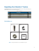
Chapter 3 Peripherals Chapter contents Introduction ..........................................................................................................................................................13 Connecting the monitor ........................................................................................................................................13 Connecting the USB ........................................................................................................................
NanoServ™ User Manual 3 • Peripherals Introduction This chapter shows how to connect various devices to the NanoServ™ System. Connect all the devices you will be using before turning on the power. The power adaptor should be connected last. The Interconnecting cables shall be acceptable for external use and shall be rated for the proper application with respect to voltage, current, anticipated temperature, flammability, and mechanical serviceability Connecting the monitor Table 2.
NanoServ™ User Manual 3 • Peripherals Connecting to the USB, Speaker/Earphone and Internet/Intranet Table 4. Connecting the USB, Speaker/Earphone and Internet/Intranet USB Port The second USB port is available on the back of the unit for connecting USB devices. Connecting to the Internet/Intranet There is an available RJ-45 10/100 Ethernet jack for connection to the hub of your intranet; and via your server for internet service (see the diagram for the RJ-45 10/100 Ethernet jack on page 40).
NanoServ™ User Manual 3 • Peripherals Connecting the keyboard and mouse Table 5. Connecting the keyboard and mouse Describing Mouse Actions Description Point - Slide and point your mouse to your desired position Click - Press the left button once. Double-click - Press the left button twice. Right-click - Press the right button once. When selecting (most) programs, this action displays a shortcut menu.
NanoServ™ User Manual 3 • Peripherals Connecting the Printer Port Table 6. Connecting the printer port Printer port POWER SW DC-IN 5V The DB-25 printer port is available on the back of the thin system unit. It is used for connecting to a printer.
NanoServ™ User Manual 3 • Peripherals Connecting the power adaptor There is a difference between the power switch on the rear panel and the system switch on the front panel. The system switch allows the NanoServ™ to suspend or sleep. The power switch supplies power to the NanoServ™. Table 7. Connecting the power adaptor DC-IN 5V POWER SW Power Adaptor To use your NanoServ™ immediately, use the supplied AC adapter as a power source. See the diagram on the left.
Chapter 4 BIOS Chapter contents Reconfiguring the system.......................................................................................................................................
NanoServ™ User Manual 4 • BIOS Reconfiguring the system 1. Note that the AMI BIOS is used in the system. To reconfigure the NanoServ™, depress or hit the key to enter your BIOS setup main menu. 2. Select a setup from the menu. 3. Press to go back to the main menu. 4. Move your cursor to “Save Settings and Exit”, and press “Y” to save the changes that you made. The system will restart automatically according to your new setup. Figure 7.
Chapter 5 Taking Care Of Your NanoServ™ Chapter contents Storing...................................................................................................................................................................21 Using cables for connection ...................................................................................................................................22 Cleaning your NanoServ™ ..............................................................................................
NanoServ™ User Manual 5 • Taking Care Of Your NanoServ™ Storing • Do not place your NanoServ™ in a location that is subject to: - Heating sources, such as a stove, oven, heater, radiator or air duct - Direct contact from sunlight - Rain or moisure - Excessive dust accumulation - High humidity - Constant or occasional mechanical movement, vibration or shock - Strong magnets, magnetic fields or magnetically unshielded speakers - Ambient temperature of more than 95ºF (35ºC) or less than 32ºF (0ºC) • Do not p
NanoServ™ User Manual 5 • Taking Care Of Your NanoServ™ Using cables for connection • To avoid problems, use only the specified interface cables that match the system. The supplier will not be responsible for problems caused by improper connection with other devices or cables. • Do not use cut or damaged cables to connect devices to the NanoServ™.
Chapter 6 Troubleshooting Chapter contents Troubleshooting your system.................................................................................................................................24 A. The NanoServ™ does not start ..................................................................................................................24 B. BIOS Error Message ...................................................................................................................................24 C.
NanoServ™ User Manual 6 • Troubleshooting Troubleshooting your system This section describes the techniques of resolving some basic problems that you may encounter when using your NanoServ™. For more troubleshooting guidelines, see “Contacting Patton for assistance” on page 27. A. The NanoServ™ does not start • Make sure that the NanoServ™ is properly secured and plugged into a power source before it is turned on. Make sure the power indicator shows the power is on.
NanoServ™ User Manual 6 • Troubleshooting C. “Operating System Not Found” - A message indicating that “Operating system not found” appears when the NanoServ™ starts (Windows won’t start). - Often this message says that an unformatted blank hard disk or blank IDE flash module is installed. In this case, there is no problem, just load your desired operating system on the disk or flash. Enter your BIOS setup main menu by pressing the key. (Be sure that your C: drive is enabled).
Chapter 7 Contacting Patton for assistance Chapter contents Introduction ..........................................................................................................................................................34 Contact information..............................................................................................................................................34 Patton support headquarters in the USA .............................................................................
NanoServ™ User Manual 7 • Contacting Patton for assistance Introduction This chapter contains the following information: • “Contact information”—describes how to contact Patton technical support for assistance. • “Warranty Service and Returned Merchandise Authorizations (RMAs)”—contains information about the warranty and obtaining a return merchandise authorization (RMA). Contact information Patton Electronics offers a wide array of free technical services.
NanoServ™ User Manual 7 • Contacting Patton for assistance Out-of-warranty service Patton services what we sell, no matter how you acquired it, including malfunctioning products that are no longer under warranty. Our products have a flat fee for repairs. Units damaged by lightning or other catastrophes may require replacement.
Appendix A Factory Defaults Chapter contents BIOS Defaults .......................................................................................................................................................30 Fedora Core 5 Install Defaults ...............................................................................................................................
NanoServ™ User Manual A • Factory Defaults BIOS Defaults Note Only items changed from the received bios are listed. 1. PCI / Plug and Play Setup 1. "Plug and Play Aware O/S": Yes 2. "PCI / Plug and Play Setup": 8MB Fedora Core 5 Install Defaults Note Fedora Core 5 is only pre-installed on NanoServ™ Model 6075. 1. Language: English 2. Keyboard: U.S. English 3. Partitioning: – 1. Ext3 partition at /boot at 100MB (set as primary partition) – 2. Swap partition at 1.5 times RAM (768MB min) – 3.
Appendix B Specifications Chapter contents Compliance ...........................................................................................................................................................32 EMC ...............................................................................................................................................................32 Safety ...............................................................................................................................
NanoServ™ User Manual B • Specifications Compliance EMC • FCC Part 15, Class A • EN55022, Class A • EN55024 Safety • IEC/EN 60950-1 Radio and TV interference This equipment generates and uses radio frequency energy, and if not installed and used properly—that is, in strict accordance with the manufacturer's instructions—may cause interference to radio and television reception.
NanoServ™ User Manual B • Specifications System Specifications Table 8. System Specifications for the NanoServ™ CPU Keyboard and Mouse VIA EDEN N Nano 800MHz PS/2 Keyboard Port PS/2 Mouse Port North/South Bridge VIA CLE266 + VT8235 Chipsets On-Board IDE Main Memory 256MB BIOS “Plug and Play” function, auto-search devices. Provide DMI for system management. Advanced ACPI configuration and power control interface. Intelligent control system. VGA AGP Rev.2.
NanoServ™ User Manual B • Specifications Technical Specifications Table 9. Technical specifications for the NanoServ™ Features CPU BIOS System Chipset I/O Chip System Memory Expansion I/O MIO Description Onboard VIA EDEN N Nano processor 800MHz AMI BIOS VIA CLE266 / VT8235 VT1211 Onboard 256MB DDR266 1xX-PCI connector (use with optional custom case) 1x EIDE (Ultra DMA 133), 1xLPT and 1x RS-232a, 1x PS/2 K/B, 1x PS/2 Mouse 2x USB 2.
NanoServ™ User Manual B • Specifications Model Numbers Table 10.
Appendix C NanoServ™ System Connectors Chapter contents NanoServ™ System Connectors Summary ...........................................................................................................36 Rear Connectors Outline for the Ultra-Thin System .............................................................................................36 Rear Connectors Outline for the Thin System.......................................................................................................
NanoServ™ User Manual C • NanoServ™ System Connectors NanoServ™ System Connectors Summary Table 11. Connectors Summary Number J1 J2 J3 J4 J5 J6, J7 Description 10/100 Ethernet IDE Connector VGA Connector USB1 (Front) USB (Back) PS/2 Keyboard & Mouse J8 PRN (Printer) J9 COM1 /RS-232 J11, J13 Line-Out, MIC J12, J19 Line-In, SB5V J15 RST (Reset) J17 DC5V Input J18 X-PCI SP1 Buzzer Type of Connections Pin Number RJ-45 jack Box Header, 22x2-2.
NanoServ™ User Manual C • NanoServ™ System Connectors Rear Connectors Outline for the Thin System Power Supply Switch PS/2 Keyboard VGA USB Line-Out DC-IN 5V POWER SW COM1 DC Power Jack PS/2 Mouse MIC-IN RJ-45 LAN Jack Printer Port Serial Port Figure 9.
NanoServ™ User Manual C • NanoServ™ System Connectors Pin Assignments Table 12. J6: KBD (PS/2 Keyboard & Mouse) - 6-pin Mini-Din Connector Pin # Signal Name 2 1 6 3 5 4 1 2 3 4 5 6 7 KBCLK PMCLK GND KBDAT PMDAT SB5V GND 8 9 GND GND Table 13. J7: Mouse(PS/2 Mouse) - 6-pin Mini-Din Connector Pin # Signal Name 2 1 6 3 5 4 1 2 3 4 5 6 7 8 9 PMCLK NC GND PMDAT NC SB5V GND GND GND Table 14.
NanoServ™ User Manual C • NanoServ™ System Connectors Table 15. J17: DC-IN (DC-IN 5V) - 3-pin MINI-DIN Lock Pin Socket Pin # Signal Name 3 1 2 1 2 3 4 J23-pin 1 & 2 SB5V NC GND Table 16. J4: USB1 (USB1x90º) 4-pin USB Type 1 Connector (Vertical Type) Pin # Signal Name 1 2 3 4 5 6 7 8 4 1 VCC USB0USBO+ GND GGND GGND GGND GGND Table 17.
NanoServ™ User Manual C • NanoServ™ System Connectors Table 19. J6: KBD (PS/2 Keyboard & Mouse) - 6-pin Mini-Din Connector Pin # Signal Name 1 2 3 4 5 LINE-OUT GND LOUTL Open Touch Open Touch VREFOUT Table 20. J9: COM1 - 9pin D-Sub Connector Pin # Signal Name Pin # Signal Name 1 3 5 7 9 5 1 6 9 DCD1 TXD1 GND RTS1 RI1 2 4 6 8 - RXD1 DTR1 DSR1 CTS1 - Table 21.
NanoServ™ User Manual C • NanoServ™ System Connectors Table 23.