USER MANUAL MODEL 1010A Miniature, High Speed Short Range Modem with Transformer Isolation Part# 07M1010A-A Doc# 039011UA Revised 11/8/95 SALES OFFICE (301) 975-1000 TECHNICAL SUPPORT (301) 975-1007
1.0 WARRANTY INFORMATION APPENDIX D BLOCK DIAGRAM Patton Electronics warrants all Model 1010A components to be free from defects, and will—at our option—repair or replace the product should it fail within one year from the first date of shipment. This warranty is limited to defects in workmanship or materials, and does not cover customer damage, abuse or unauthorized modification. If this product fails or does not perform as warranted, your sole recourse shall be repair or replacement as described above.
2.0 GENERAL INFORMATION Thank you for your purchase of this Patton Electronics product. This product has been thoroughly inspected and tested and is warranted for One Year parts and labor. If any questions or problems arise during installation or use of this product, please do not hesitate to contact Patton Electronics Technical Support at (301) 975-1007.
3.0 CONFIGURATION APPENDIX B SPECIFICATIONS Transmission Format: Asynchronous, full duplex Transmission Line: Two unconditioned twisted pair 19 - 26 AWG Range: (See table below) The Model 1010A is designed to be easy to use. There are no internal jumpers or DIP switches to set, so there is no need to open the case to configure the unit (you may need to open the case for wire connection—refer to section 4.0). The only configuration necessary for operation is proper setting of the external DCE/DTE switch.
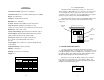
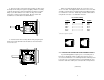
+RCV- G -XMT+ 4.0 INSTALLATION Once you have properly configured the DTE/DCE switch, you are ready to connect the Model 1010A to your system. This section tells you how to properly connect the Model 1010A to the twisted pair and RS-232 interfaces, and how to operate the Model 1010A. 10. BEND the top half of the case as necessary to place it over the strain relief assembly. Do not snap the case together yet. 4.
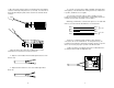
+RCV- G -XMT+ +RCV- G -XMT+ 8. Place the 2 halves of the strain relief assembly on either side of the telephone wire and press together very lightly. Slide the assembly so that it is about 2 inches from the terminal posts and press together firmly. If your cable diameter is too small or too large for our strain relief, please contact our technical support. We have strain relief assemblies to accommodate most cable diameters. When connecting two Model 1010As, it is necessary to use a "cross over" cable.
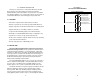
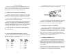
4. Connect one pair of wires to XMT+ and XMT- (transmit positive and negative) on the terminal block, making careful note of which color is positive, and which color is negative. 1. Open the unit by gently inserting a screw driver between the DB-25 connector and the lip of the plastic case (see below). You don't have to worry about breaking the plastic, but be careful not to bend the D-sub connector. 5.