USER MANUAL MODEL 1025 and 1025S Synchronous Short Range Modem with Clocking Options Part #07M1025-C Doc. #041012UC Revised 4/20/98 CERTIFIED An ISO-9001 Certified Company SALES OFFICE (301) 975-1000 TECHNICAL SUPPORT (301) 975-1007 http://www.patton.
1.0 WARRANTY INFORMATION 1.3 SERVICE Patton Electronics warrants all Model 1025 components to be free from defects, and will—at our option—repair or replace the product should it fail within one year from the first date of shipment. This warranty is limited to defects in workmanship or materials, and does not cover customer damage, abuse or unauthorized modification. If this product fails or does not perform as warranted, your sole recourse shall be repair or replacement as described above.
2.0 GENERAL INFORMATION 3.0 CONFIGURATION Thank you for your purchase of this Patton Electronics product. This product has been thoroughly inspected and tested and is warranted for One Year parts and labor. If any questions or problems arise during installation or use of this product, please do not hesitate to contact Patton Electronics Technical Support at (301) 975-1007. The Model 1025 provides six configuration switches which allow selection of clocking method, RTS/CTS delay and data rate.
3.2 SWITCH SETTINGS Switches 4, 5 and 6: Data Rate All possible settings for the Model 1025’s configuration switches are presented in the summary table and descriptions below. If you have additional questions regarding configuration, contact Patton Technical Support at (301) 975-1007. Switches 4 thru 6 are set in combination to allow the Model 1025 to be used at data rates from 1.2 to 19.2 Kbps.
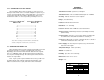
4.0 INSTALLATION Once the Model 1025 is properly configured, it is ready to connect to your system. This section tells you how to properly connect the Model 1025 to the twisted pair and RS-232 interfaces, and how to operate the Model 1025. When connecting two Model 1025s, it is necessary to use a “crossover” cable. The diagram below shows how a crossover cable should be constructed for an environment where both Model 1025s use a 6-wire RJ-11 connector.
1. Open the unit by gently inserting a screwdriver between the DB-25 connector and the lip of the plastic case (see below). You don’t have to worry about breaking the plastic, but be careful not to bend the D-sub connector. 4. Connect one pair of wires to the two XMT (transmit) poles on the terminal block. The Model 1025 is not polarity sensitive, so either wire may connect to either pole. 5. Connect the other pair of wires to the two RCV (receive) poles on the terminal block.
8. Place the 2 halves of the strain relief assembly on either side of the telephone wire and press together very lightly. Slide the assembly so that it is about 2 inches from the terminal posts and press together firmly. If your cable diameter is too small or too large for our strain relief, please contact our technical support. We have strain relief assemblies to accommodate most cable diameters. 10. Place the top half of the case as necessary to slide it over the strain relief assembly.
APPENDIX A SPECIFICATIONS 4.2.2 CONNECTION TO A “DCE” DEVICE Since the Model 1025 is wired as a DCE, you cannot connect it directly to another DCE such as a modem, multiplexer or printer. If you need to connect the Model 1025 to another DCE device, you must use a null modem cable wired according to diagram below. We recommend that the cable is as short as possible, preferably 6 feet or less.
APPENDIX B RS-232 PIN CONFIGURATIONS DIRECTION “DCE” STANDARD SETTING From Model 1025 Transmitting Timing - 15 From Model 1025 Receiver Timing - 17 To Model 1025 Data Term.