
- Patton Electronics AC Powered, Asynchronous Short Range Modem USER MANUAL1050


4.0 INSTALLATION
The Model 1050 is easy to install. After configuring the unit
properly, you will need to connect the two twisted pairs and the RS-232
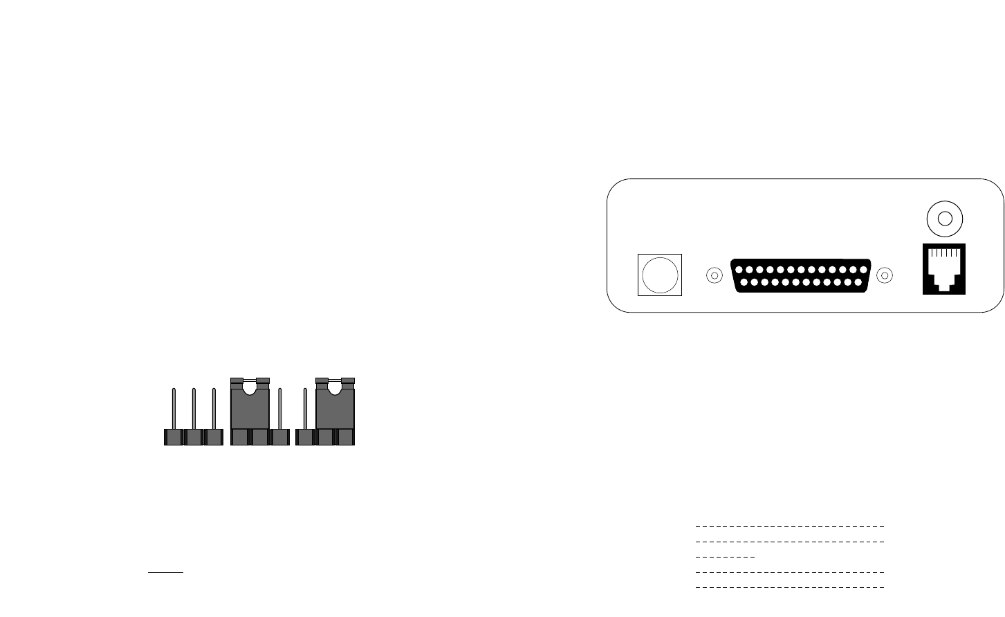
cable. Figure 2 (below) shows the rear panel location of the RJ-11 jack
and strain relief grommet (line connections), as well as the female DB-
25 (RS-232 connection).
Figure 3. Rear view of 1050 showing interface connectors
4.1 TWISTED PAIR WIRING OVERVIEW
These short range modems are designed to work in
pairs
. You will
need one at each end of a 4-wire twisted pair circuit. The pairs must be
"dry" (unconditioned) metallic wire, 19 - 26 AWG. The smaller gauges
limit distance somewhat compared with larger gauges. When you have
completed wiring for your data circuit, the pin connections should be as
shown below:
4.1.1 TWISTED PAIR CONNECTION USING TERMINAL BLOCKS
The Model 1050 terminal block is located on the PC board inside
the unit. To access the PC board, remove the two screws on the back
panel and slide the PC board out of the case. Connect the bare twisted
pair wires by first inserting them through the grommet on the back
panel, then stripping the ends and connecting the individual leads to
the terminal block. Be sure the end-to-end connections follow the
diagram above.
6
3.2 SETTING THE DCE/DTE SWITCH
Correct setting of the DCE/DTE switch eliminates the need for RS-
232 crossover cables. If the RS-232 device you are connecting to the
Model 1050 is a PC, terminal or host, or is wired like one, set the
DCE/DTE switch to "DCE". If the RS-232 device you are connecting to
the Model 1050 is a modem or multiplexer, or is wired like one, set the
DCE/DTE switch to "DTE".
3.3 SETTING THE CARRIER CONTROL STRAP (see Note 2)
The setting of the carrier control strap determines whether carrier
is “constantly on” or “controlled by RTS”. For “controlled by RTS”
position the strap on pegs 1 & 2. For “constantly on” position the strap
on pegs 2 & 3. Figure 2 (below) shows the two possible settings of the
carrier control strap.
NOTE 1: If you are connecting twisted pair to the Model 1050
using the internal terminal blocks, make the twisted pair
connection before
re-inserting the PC board into the case. See
Section 4.1.1 for details on twisted pair connection.
NOTE 2: If you are using the Model 1050 in a multipoint
application, consult Section 4.2 for proper Master and Slave carrier
control settings.
XMT + RCV+
XMT - RCV -
GG
RCV - XMT -
RCV + XMT +
To Shield (Optional)
}
One Pair
}
One Pair
5
RS-232 Interface
Made In The USA
LinePower
Powered Async. Short
Range Modem
Figure 2 Model 1050 strap settings
123 123 123