USER MANUAL MODEL 1069 OnSite™ VDSL2 CPE REGULATORY MODEL NUMBER: 03342D4-001 This is a Class A device and is not intended for use in a residential environment. Part# 07M1069-UM Rev.
CONTENTS 1.0 1.1 1.2 1.3 1.4 1.5 1.6 Warranty Information ................................................................. Regulatory Information ................................................................. EMC Directive:.............................................................................. Low-Voltage Direcive (Safety): ..................................................... PSTN: ...........................................................................................
1.0 WARRANTY INFORMATION Patton Electronics warrants all Model 1069 components to be free from defects, and will—at our option—repair or replace the product should it fail within one year from the first date of the shipment. This warranty is limited to defects in workmanship or materials, and does not cover customer damage, abuse or unauthorized modification. If this product fails or does not performs as warranted, your sole recourse shall be repair or replacement as described above.
of Part 15 of FCC rules, which are designed to provide reasonable protection from such interference in a commercial installation. However, there is no guarantee that interference will not occur in a particular installation.
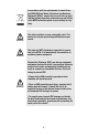
1.6 SAFETY WHEN WORKING WITH ELECTRICITY • This device contains no user serviceable parts. This device can only be repaired by qualified service personnel. • Do not open the device when the power cord is connected. For systems without a power switch and without an external power adapter, line voltages are present within the device when the power cord is connected. • For devices with an external power adapter, the power adapter shall be a listed Limited Power Source.
In accordance with the requirements of council directive 2002/96/EC on Waste of Electrical and Electronic Equipment (WEEE), ensure that at end-of-life you separate this product from other waste and scrap and deliver to the WEEE collection system in your country for recycling. WARNING WARNING This device contains no user serviceable parts. This device can only be repaired by qualified service personnel. This device is NOT intended nor approved for connection to the PSTN.
2.0 GENERAL INFORMATION Thank you for your purchase of this Patton Electronics product. This product has been thoroughly inspected and tested and is warranted for one year for parts and labor. If any questions or problems arise during installation or use of this product, contact Patton Electronics Technical Support at +1 (301) 975-1007. 2.
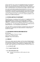
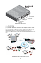
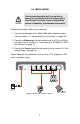
DN /IS TS PO h3 Et h2 Et h1 Et h0 Et 12 VD C POTS/ISDN twisted-pair RJ-45 interface VDSL twisted-pair RJ-45 interface 1A Ethernet ports (0-3) Reset switch Power jack Figure 1. Model 1069 rear panel 2.3 APPLICATION In an example application, the VDSL2 CPE modem is placed in either MxU environments or individual residents for delivering triple play services including “fiber like” high-speed broadband service. Built-in POTS/ISDN splitters allow for both data and voice to be broken out at the CPE.
3.0 INSTALLATION CAUTION The Interconnecting cables shall be acceptable for external use and shall be rated for the proper application with respect to voltage, current, anticipated temperature, flammability, and mechanical serviceability. To connect the Model 1069, do the following: 1. Connect the Line port of the Model 1069 with a telephone cable (refer to section 3.1, “Connecting the Line Interface” on page 10). 2.
3.1 CONNECTING THE LINE INTERFACE CAUTION The Interconnecting cables shall be acceptable for external use and shall be rated for the proper application with respect to voltage, current, anticipated temperature, flammability, and mechanical serviceability. The Model 1069 supports communication over a distance of up to 10,000 ft (3 km) over 24 AWG (0.5 mm) twisted-pair wire or Cat5+. Note Actual distance and link performance may vary depending on the environment and type/gauge of wire used.
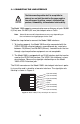
3.2 CONNECTING THE 10/100BASE-T ETHERNET INTERFACE CAUTION The Interconnecting cables shall be acceptable for external use and shall be rated for the proper application with respect to voltage, current, anticipated temperature, flammability, and mechanical serviceability. The RJ-45 ports labeled Ethernet are the Auto-MDIX10/100Base-T interface. These ports are designed to connect directly to a 10/100Base-T device or network. Figure 5 shows the signal/pin relationships on this interface.
3.4 CONNECTING POWER CAUTION The Interconnecting cables shall be acceptable for external use and shall be rated for the proper application with respect to voltage, current, anticipated temperature, flammability, and mechanical serviceability. The Model 1069 does not have a power switch, so it powers up as soon as it is plugged in. An external AC or DC power supply is available separately. This connection is made via the barrel jack on the rear panel of the Model 1069.
5.0 OPERATION Once the Model 1069 is properly installed, it should operate transparently. No user settings required. This section describes reading the LED status monitors. Before applying power to the Model 1069, please review section 3.4, “Connecting Power” on page 12 to verify that the unit is connected to the appropriate power source. 5.
APPENDIX A SPECIFICATIONS A.1 VDSL2 • Full compliance up to 30Mhz profile A.2 LAN CONNECTION • Four RJ-45, 10/100Base-T, IEEE 802.3 Ethernet A.3 TRANSMISSION LINE • Two-wire unconditioned twisted pair • VDSL2 Connector: RJ-45 A.4 LED STATUS INDICATORS • Power (Green) • VDSL2: Link (Green) • Local (Green) • Remote (Green) • Ethernet: Link (Green) & Activity (Flashing Green) A.
APPENDIX B MODEL 1069 SERIES FACTORY REPLACEMENT PARTS AND ACCESSORIES Patton Model # Description Base Models 1069/EUI OnSite VDSL2 CPE RJ45 Line, 100-240VAC 07M1069-UM User Manual Power Supplies PS-03671H1-002 100-240VAC (12V, DC/2A) Wall mount power adapter Power Adapters 12-130 European replacement plug 12-129 American replacement plug 12-131 United Kingdom plug 12-132 Australian/Chinese plug 15
APPENDIX C MODEL 1069 SERIES INTERFACE PIN ASSIGNMENT C.1 10/100BASE-T INTERFACE RJ-45 • Pin 1: TX+ • Pin 2: TX• Pin 3: RX+ • Pin 6: RX• Pins 4, 5, 7, 8: no connection C.2 VDSL2 INTERFACE RJ-45 • Pin 4: RING • Pin 5: TIP • Pins 1, 2, 3, 6, 7, 8: no connection C.3 POTS/ISDN INTERFACE RJ-45 • Pin 4: 2-wire RING • Pin 5: 2-wire TIP • Pins 1, 2, 3, 6, 7, 8: no connection Copyright © 2011. Patton Electronics Company All Rights Reserved.