USER MANUAL MODEL 2710 Series NetLink-T1™ T1/Fractional T1 CSU/DSU CERTIFIED An ISO-9001 Certified Company Part# 07M2710 Doc# 08604U2-001 Rev. C Revised 06/19/06 SALES OFFICE (301) 975-1000 TECHNICAL SUPPORT (301) 975-1007 http://www.patton.
TABLE OF CONTENTS Section 1.0 GENERAL INFORMATION Page 1.0 General Information...............................................................2 1.1 Warranty Statement 1.2 CE Notice 1.3 Radio and TV Interference 1.4 FCC Information 1.4.1 FCC Compliance 1.5 Industry Canada Notice 1.6 Service Information 2.0 General Information...............................................................6 2.1 Features 2.2 General Product Description 2.3 Supported Applications 2.3.
1.3 RADIO AND TV INTERFERENCE 1.4.1 FCC Compliance: The NetLink-T1™ Model 2710 Series generates and uses radio frequency energy, and if not installed and used properly—that is, in strict accordance with the manufacturer's instructions—may cause interference to radio and television reception.
2.0 GENERAL INFORMATION 1.6 SERVICE INFORMATION All warranty and non-warranty repairs must be returned freight prepaid and insured to Patton Electronics. All returns must have a Return Materials Authorization number on the outside of the shipping container. This number may be obtained from Patton Electronics Technical Support at: tel: (301) 975-1007 email: support@patton.com www: http://www.patton.com NOTE: Packages received without an RMA number will not be accepted.
3.0 CONFIGURATION 2.3 SUPPORTED APPLICATIONS The NetLink-T1™ CSU/DSU provides a T1 (DS1) network termination between the service provider and customer premises equipment (CPE) such as a router. The Netlink-T1™ can also be used as a highspeed short haul modem for campus applications. The Model 2710 features configuration capability via hardware switches or a software control port. This section describes all possible hardware and software switch configurations of the NetLink-T1™. 3.
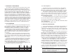
Switch SW4: Line Framing and Coding SWITCH SET SUMMARY TABLE Position Function Factory Default Selected Option SW1 Data Rate On SW2 Data Rate On SW3 Data Rate On SW4 Framing & Coding Off ESF/B8ZS SW5 DS Zero Rate On 64 kbps SW6 Clock Mode Off Network SW7 Line Build Out Off SW8 Line Build Out Off 1.536 Mbps (DTE Rate) 0dB Use Switches SW1, SW2 and SW3 to set the DTE data rate. Each setting represents an nx56/nx64 setting.
Switch SW6: Clock Mode 3.2 SOFTWARE CONFIGURATION Set Switch SW6 to determine the 2710’s transmitter timing. SW6 Off On Clock Mode Network Clock. Transmitter timing is derived from the received line signal. Internal Clock. Transmitter clock is derived from an internal oscillator. The NetLink-T1™ features a menu-driven command system that allows you to monitor/configure its operating parameters.
4) When the unit is first turned on, the terminal screen may appear blank. Press the key. If your serial connection is good, then the unit will immediately display a password prompt. The following message will appear in the middle of the screen: 3.2.1 Introduction to Main Menu After entering the password, you may access all of the system’s functions and parameters. The Main Menu looks like this: Patton Electronics Menu Management Enter Password: _ 5) Type in the password and press .
The Main Menu options are briefly described below. a System Configuration options allow you to change various aspects of the NetLink-T1™’s operation, e.g., framing, line coding, and aggregate bandwidth. b System Diagnostics/Statistics options allow you to monitor the network performance, initiate V.54 loops, local loops, and send test patterns. Network performance parameters are updated once a second, giving you the ability to quickly determine if there is a problem.
ESF: This stands for Extended Superframe Format, a line format developed by AT&T. AT&T Technical Reference 54016 (TR 54016) defines the ESF, a format which is commonly used to allow monitoring of the network interface performance over the Facility Data Link (FDL). AT&T TR 62411 says, “the Extended Superframe Format “extends” the DS1 superframe structure from 12 to 24 frames…for a total of 4632 bits.
d Clocking: Network (default) Options: f Options: ANSI T1.403, AT&T TR54016 Network, Internal, External Network: This is the most commonly used setting when connect ing to a carrier’s network. In this mode, the unit recovers the clock from the received signal and uses it to transmit data. In this way the unit remains synchronized to a master clock. In campus applications, one of the units must be set to Internal clock, and the other end is set to Network clock.
h Remote In-band Loops: Enabled (default) n DS0 Channel Configuration Menu [ Bandwidth/# Channels = 1,536/24 ] (default) Options: Enabled, Disabled In ESF, D4 and Unframed formats, the unit can respond to special repeating codes in the data stream that represent loopback commands. The command to loop up (go into loopback) is a repeating pattern of 00001s. This pattern overwrites the normal data.
3.2.3 System Diagnostics b The System Diagnostics/Statistics screen looks like this: The Remote Digital Loopback (RDL) test checks the performance of both the local and remote NetLink-T1™s, as well as the communication link between them. Data from the local DTE is sent across the entire communication circuit and looped back to the local DTE. The NetLink-T1™ Initiating a RL can be in one of the following states: OK NOTE: This screen is updated once per second.
The NetLink-T1™ receiving a RL can be in one of the following states: c RxPr The NetLink-T1™ is receiving a preparatory pattern. Sack The NetLink-T1™, upon receiving a preparatory pattern, sends an acknowledgement message. RL The NetLink-T1™ is in remote loopback mode. RxTr The NetLink-T1™ is receiving a terminate loopback message. Wt1s The NetLink-T1™ is waiting for a sequence of all ones and will time out if it does not receive it. IdleP The NetLink-T1™ is sending a QRSS, 511 or 2047 pattern.
Receive Alarm Indication [RAI] indicates that the local unit is receiving a Yellow Alarm. This alarm is sent by the remote unit or the central office when it loses the received signal. This indicates the local unit’s transmitted signal is not reaching the remote unit. Rx Level The Model 2710 displays the current received signal strength in dB. There are four level ranges detected: +2 to –7.5 -7.5 to –15 -15 to –22.5 < -22.
c 3.2.4 Unit Options The Unit Options screen looks like this (factory default): Loop Timeout The Loop Timeout setting can be set to one of the following: 00:05 = 00:10 = 00:15 = 00:30 = 00:45 = 01:00 = 01:30 = 02:00 = 03:00 = NEVER = d five minutes ten minutes fifteen minutes thirty minutes (default setting) forty-five minutes one hour 90 minutes two hours three hours forever—the unit will remain in loopback without user intervention.
4.0 INSTALLATION 4.3 POWER CONNECTION The NetLink-T1™ is equipped with DTE, network, and power interfaces. This section briefly describes connection to each. The NetLink-T1™ offers three ways to supply external power: AC power, DC power and interface power. 4.1 DTE INTERFACE CONNECTION 4.3.1 Using the AC Power Supply (120VAC or 100-240VAC) The DTE interface is a V.35 DCE presented as an M/34 male connector. This interface is designed to plug directly into a DTE interface (See Appendix D for V.
5.0 OPERATION Once the NetLink-T1™ is installed and configured properly it is ready to place into operation. This section describes the function of the LED indicators, and the use of the loopback and pattern test modes. LOS The Loss of Sync LED lights when the unit loses synchronization with the incoming signal. This may happen when there is a framing mismatch or a loss of signal. In unframed mode, the LOS LED monitors the status of the transmit clock.
5.2 LOOP (V.54 & TELCO) DIAGNOSTICS To perform an RDL test, follow these steps: The NetLink-T1™ offers three V.54 loop diagnostics and is compatible with two Telco loop diagnostics. Use these diagnostics to test the CSU/DSU and any communication links. These tests can be activated via the software control port (See Section 3.2.3 System Diagnostics) or via signals on the serial port interface. 1. 5.2.
APPENDIX A 5.3 BIT ERROR RATE (V.52) DIAGNOSTICS PATTON NETLINK-T1 MODEL 2710 The NetLink-T1™ offers three V.52 Bit Error Rate (BER) test patterns. These test patterns may be invoked along with the LAL and RDL tests to evaluate the unit(s) and the communication links. When a 511, 2047, or QRSS test is invoked, the NetLink-T1™ 20 generates a pseudo-random bit pattern of 511 bits, 2047 bits or 2 bits, respectively, using a mathematical polynomial.
APPENDIX B APPENDIX C PATTON NETLINK-T1™ MODEL 2710 PATTON NETLINK-T1™ MODEL 2710 CABLE RECOMMENDATIONS FACTORY REPLACEMENT PARTS AND ACCESSORIES The Patton NetLink T1™ Series has been performance tested by Patton technicians using twisted-pair cable with the following characteristics: Wire Gauge Capacitance Resistance 19 AWG 22 AWG 24 AWG 83nf/mi or 15.72 pf/ft. 83nf/mi or 15.72 pf/ft. 83nf/mi or 15.72 pf/ft. .0163 Ohms/ft. .0326 Ohms/ft. .05165 Ohms/ft.
APPENDIX D APPENDIX D PATTON NETLINK-T1™ MODEL 2710 (continued) INTERFACE PIN ASSIGNMENT PATTON NETLINK-T1™ MODEL 2710 RJ-48C T1 (DS0) Network Interface (Female Modular Jack) INTERFACE PIN ASSIGNMENT M/34 Connector, Terminal Interface Pin # Pin # 1 2 4 5 Signal RX Data (RING) RX Data (TIP) TX Data (RING) TX Data (TIP) } } From Network To Network TRS Jack (RS-232 Control Port Pin # Tx Data Rx Data Sleeve Signal Source From Model 2710 To Model 2710 N/A RS-232 Control Port (Signals at DB-25 Conn
APPENDIX E PATTON NETLINK-T1 MODEL 2710 POWER SUPPLY INTERFACE Via Main 5VDC power jack (J1) Center Pin: +5VDC @ 300 mA Outer Barrel: Ground Jumper Position for Power via DC Power Jack (default): Via Auxiliary Power Supplied to Pin KK on V.35 connector DC Power supplied to pin KK must be 5VDC ± 5%, 300mA minimum. Jumper Position for Power via Pin KK: NOTE: NetLink-T1™ is factory configured to accept power from the enclosed DC wall adapter (See Sections 4.3.1 and 4.3.2 above).