
- Patton Electronics Server User Manual

Configuring Frame Relay 318
Access Server Administrators’ Reference Guide C • Technical Reference
The following settings must match the line configuration provided by the local telephone company. For more
information on setting up your T1/E1, see the Model 29xx Series RAS User Manual available online at
www.patton.com/manuals/29xx.pdf.
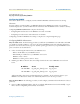
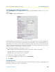
4. Click on the
Line Type
drop-down menu and choose one of the following options:
– For a T1 line, select
dsx1ESF(2)
(Extended SuperFrame DS1) or
dsx1D4(3)
(A&T D4 format DS1).
– For an E1 line, choose
dsx1E1(4)
or
dsx1E1-CRC(5)
.
5. Click on the
Line Coding
drop-down menu and choose one of the following options:
– For T1: If you selected dsx1D4(3) line type, select
dsx1AMI(5)
line coding. If you selected dsx1ESF(2)
line type, choose
dsx1B8ZS(2)
line coding.
– For E1: Select
dsx1AMI(5)
or
dsx1HDB3(3)
. Most installations will use HDB3.
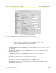
6. Click on the
Line Build Out
drop-down menu and choose one of the following options:
– For T1: Select
t1pulse0dB(2)
.
– For E1, select
e1pulse(1)
.
7. Click
Submit
.
8. Select
none
for Signalling Protocol.
9. Click
Submit
.
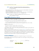
At this point, the access server’s front panel LEDs should now be showing signs that the line is active. If the phone
company line is not connected to the access server, the error indicator will glow red for that line/connection.
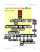
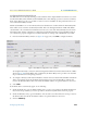
WAN Channel Assignment main screen
The next stage in configuring a Frame Relay link is to set the number of 64-kbps channels on the T1/E1 that
will carry the data. Each channel is 64 kbps in speed and must correspond to the same channels that your pro-
vider is using. Usually your provider will start from channel 1. For example: a 256-kbps link could be divided
into 64-kbps channels numbered 1, 2, 3, and 4.
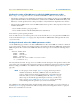
To set the channel assignment:
1. Click on
T1/E1 Link
under the
Configuration Menu
to display the
T1/E1 Link Activity
main window (see
figure 102 on page 252).
2. Click on
Channel Assignment
in the appropriate Link: x section (for example, if the T1/E1 cable was con-
nected to port 2, you would click on
Channel Assignment
in the Link: 2 section).
3. Click on the appropriate channel’s drop-down menu and select
frameRelay(3)
.
4. Repeat step 3 to configure remaining channels.
5. Click
Submit
.
The link should now be activated on your access server. The next stages will configure Frame Relay and IP
routing.