USER MANUAL MODEL IM1/I4 Ethernet Bridge with Integral 4-Port Hub QuikConnect™ Module Part# 07MIM1/I4-C Doc# 090141UC Revised 07/19/00 CERTIFIED An ISO-9001 Certified Company SALES OFFICE (301) 975-1000 TECHNICAL SUPPORT (301) 975-1007 http://www.patton.
1.0 WARRANTY INFORMATION 1.3 SERVICE Patton Electronics warrants all Model IM1/I4 components to be free from defects, and will—at our option—repair or replace the product should it fail within one year from the first date of shipment. This warranty is limited to defects in workmanship or materials, and does not cover customer damage, abuse or unauthorized modification. If this product fails or does not perform as warranted, your sole recourse shall be repair or replacement as described above.
2.0 GENERAL INFORMATION Thank you for your purchase of this Patton Electronics product. This product has been thoroughly inspected and tested and is warranted for One Year parts and labor. If any questions or problems arise during installation or use of this product, please do not hesitate to contact us at: (301) 975-1007, http://www.patton.com; support@patton.com. 2.3 TYPICAL APPLICATION The Model IM1/I4 QuickConnect™ is designed to plug directly into the rear of a Patton Electronics baseband modem (e.g.
Patton IM1/I4 Bridge 3.0 PPP OPERATIONAL BACKGROUND PPP is a protocol used for multi-plexed transport over a pointto-point link. PPP operates on all full duplex media, and is a symmetric peer-to-peer protocol, which can be broken into three main components: 1. A standard method to encapsulate datagrams over serial links; 2. A Link Control Protocol (LCP) to establish, configure, and test the data-link connection; 3.
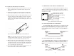
3.0 CONFIGURATION The Model IM1/14 module plugs into Patton’s fiber and copper baseband modems to provide Ethernet LAN extension. The IM1/14 has no switches or jumpers and does not need to be configured. However, factors such as type of medium, throughput across the link and clocking mode must be determined by the settings of the baseband modems. Please refer to your baseband modem (i.e. 1092A, 1095, etc) to make the following settings.
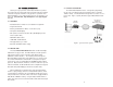
4.2 CONNECTING TO THE 10BASE-T ETHERNET PORT 4.1.2 Installing the New QuickConnect™ Module 1) Make sure the power switch on the base unit is off. Leave the power cord plugged into a grounded outlet to keep the unit grounded. 2) Hold the module with the faceplate toward you and align the module with the guide slots in the rear panel of the base unit.
N 5.0 OPERATION 4.3 CONNECTION TO THE LINE INTERFACE MEDIA Instructions for connecting the line interface media (twisted pair, or fiber optic cable) are contained within the base unit user manual. Please refer to the base unit manual for connection details. Once the Model IM1/14 is installed, it should operate transparently. This sections describes power-up, general operating instructions, and the LED status monitors. 4.4 CONNECTING TO AC OR DC POWER 5.
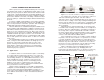
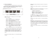
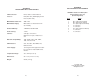
5.3 LED STATUS MONITORS The Model IM1/I4 features two LEDs that monitor general operating status and the 10Base-T twisted pair link integrity. Figure 6 (below) shows the LEDs located directly beneath the RJ-45 jack. Following Figure 6 is a description of each LEDs function. TP1 COL TP2 [Green] - On indicates that port 2 is receiving link integrity or a packet. WANF [Yellow] - On indicates that a WAN failure has occurred.
APPENDIX A PATTON MODEL IM1/I4 SPECIFICATIONS LAN Connection: RJ-45, 10Base-T, 802.