USER MANUAL MODEL IM2RC/I-100B Ethernet Bridge Module Part# 07MIM2RC-I100B-UM Rev.
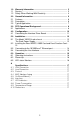
1.0 1.1 1.2 Warranty Information ................................................................. 3 Service.......................................................................................... 3 Safety When Working With Electricity .......................................... 4 2.0 2.1 2.2 2.3 General Information.................................................................... Features........................................................................................ Description..............
1.0 WARRANTY INFORMATION Patton Electronics warrants all Model IM2RC/I-100B components to be free from defects, and will—at our option—repair or replace the product should it fail within one year from the first date of the shipment. This warranty is limited to defects in workmanship or materials, and does not cover customer damage, abuse or unauthorized modification. If this product fails or does not performs as warranted, your sole recourse shall be repair or replacement as described above.
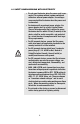
1.2 SAFETY WHEN WORKING WITH ELECTRICITY • Do not open the device when the power cord is connected. For systems without a power switch and without an external power adapter, line voltages are present within the device when the power cord is connected.
This device contains no user serviceable parts. This device can only be repaired by qualified service personnel. WARNING This device is NOT intended nor approved for connection to the PSTN. It is intended only for connection to customer premise equipment. WARNING CAUTION Electrostatic Discharge (ESD) can damage equipment and impair electrical circuitry. It occurs when electronic printed circuit cards are improperly handled and can result in complete or intermittent failures.
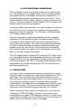
2.0 GENERAL INFORMATION Thank you for your purchase of this Patton Electronics product. This product has been thoroughly inspected and tested and is warranted for One Year parts and labor. If any questions arise during installation or use of this product, please contact Patton Electronics Technical Support at: (301) 975-1007. 2.
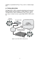
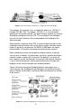
capabilities using RocketLink Plug ‘n’ Play, as well as in-band management. 2.3 TYPICAL APPLICATION The Model IM2RC/I-100B is designed to plug directly into the rear of a Patton Electronics rack card modem (i.e. Model 3088RC or 2701RC). The Model IM2RC/I-100B is designed to be used as one of a pair of units. Figure 1 (below) illustrates a typical Model IM2RC/I-100B installation. Corporate Headquarters Patton Model 3088 4.
3.0 PPP OPERATIONAL BACKGROUND PPP is a protocol used for multi-plexed transport over a point-to-point link. PPP operates on all full duplex media, and is a symmetric peer-topeer protocol, which can be broken into three main components: 1. A standard method to encapsulate datagrams over serial links; 2. A Link Control Protocol (LCP) to establish, configure, and test the data-link connection; 3. A family of Network Control Protocols (NCPs) to establish and configure different network layer protocols.
Figure 2. Cisco router with serial interface, configured as PPP Half Bridge For example, the customer site is assigned the addresses 192.168.1.1 through 192.168.1.254. The address 192.168.1.1 is also the default gateway for the remote network. The above settings remove any routing/ forwarding intelligence from the CPE. The associated Cisco configuration will set serial interface (s0) to accommodate half bridging for the above example. Authentication is optional under PPP.
4.0 CONFIGURATION The Model IM2RC/I-100B module plugs into Patton’s 3088RC and 2701RC modems to provide Ethernet LAN extension. The IM2RC/I100B has no switches or jumpers and does not need to be configured. However, factors such as the type of medium, throughput across the link and clocking mode must be determined by the settings of the baseband modems. Please refer to your baseband modem (i.e. 3088RC and 2701RC) to make the following settings. 1.
4.1 CONNECTING THE INTERFACE DRIVER BOARD This package contains an interface driver board that allows you to configure your front function card for ethernet operation. Figure 4 shows the Interface Driver Board connected to a Model 2701RC front function card. Figure 4. Model IM2RC/I-100B Driver Board mounted on Model 2701RC Follow the instructions below to connect the interface driver board to the front function card: 1.
5.0 INSTALLATION This section describes the NetLink Model 1001R14 rack chassis. Included are installation instructions for the IM2RC/I-100B rear card, plus ethernet and line interface connections to the IM2RC/I-100B card. Please refer to the appropriate function card (i.e. 3088RC) user manual to configure and install the function card. 5.1 THE MODEL 1001R14 RACK CHASSIS The Model 1001R14 Rack Chassis (Figure 5) has fourteen short range modem card slots, plus its own power supply. Measuring only 3.
5.2 INSTALLING THE REAR IM2RC/I-100B CARD AND FRONT FUNCTION CARD The Model IM2RC/I-100B is a rear-mountable ethernet interface card that works with Patton Models 3088RC and 2701RC access products. The two cards meet inside the rack chassis and plug into each other by way of mating 50 pin card edge connectors. Use the following steps as a guideline for installing each Model IM2RC/I-100B and its function card mate into the rack chassis: CAUTION The IM2RC/I-100B card contains sensitive integrated circuitry.
5.3 CONNECTING TO THE 10/100BASE-T ETHERNET PORT The Model IM2RC/I-100B provides line side connections through a terminal block or through a RJ-45 connector. Figure 6 below shows the rear panel and the locations of the connectors. RJ-45 Line Side 10/100-BaseT Connector Figure 6. IM2RC/I-100B Rear Panel The IM2RC/I-100B Ethernet interface is designed to connect directly to a 10/100Base-T network. Figure 7 shows the signal/pin relationships on this interface.
5.4 CONNECTING THE LINE INTERFACE The Model IM2RC/I-100B is to be used with Patton function card access products (i.e. 3088RC) There are two essential requirements for connecting the line interface on Model IM2RC/I-100B: 1. These units work in pairs with one IM2RC/I-100B connected to another IM2RC/I-100B over 2 or 4-Wire Twisted pair (2 or 4-Wire operation is determined by the front function card). 2.
6.0 OPERATION Once the Model IM2RC/I-100B is installed, it should operate transparently. The following sections describes the power-up, general operating instructions, and the LED status monitors. 6.1 OPERATING INSTRUCTIONS In order to operate, the Model IM2RC/I-100B must be installed in the rack unit. It also requires a 10/100Base-T connection. After power is applied, the IM2RC/I-100B automatically starts performing the bridging function without further user intervention.
APPENDIX A SPECIFICATIONS A.1 LAN CONNECTION RJ-45, 10/100Base-T, 802.3af Ethernet A.2 LINE CONNECTION RJ-45, female connector A.3 PROTOCOL PPP (RFC 1661) with Bridging Control Protocol (RFC3518) A.4 MAC ADDRESS AGING MAC addresses deleted after 6 minutes inactivity A.5 ON-BOARD MEMORY 128MB DDR2 SDRAM; 16MB FLASH A.6 INTERFACE Card-edge connection to Patton modems A.7 LED INDICATORS (1) general status; (1) link integrity A.8 POWER CONSUMPTION 200mA @ 12VDC, supplied by chassis power supply A.
NOTES _______________________________________________________ _______________________________________________________ _______________________________________________________ _______________________________________________________ _______________________________________________________ _______________________________________________________ _______________________________________________________ _______________________________________________________ _______________________________________________________ __
NOTES _______________________________________________________ _______________________________________________________ _______________________________________________________ _______________________________________________________ _______________________________________________________ _______________________________________________________ _______________________________________________________ _______________________________________________________ _______________________________________________________ __
© Copyright 2010.