USER MANUAL MODEL 2715 NetLink-E1: E1/Fractional E1 NTU CERTIFIED An ISO-9001 Certified Company Part# 07M2715-UM Doc# 08605U2-001, Rev. C Revised 10/26/06 SALES OFFICE (301) 975-1000 TECHNICAL SUPPORT (301) 975-1007 http://www.patton.
PATTON MODEL 2715 TABLE OF CONTENTS Section 1.0 GENERAL INFORMATION Page 1.0 General Information...............................................................2 1.1 Warranty Statement 1.2 Radio and TV Interference 1.3 CE and Telecommunication Approvals 1.4 Service Information 2.0 General Information........................................................5 2.1 Features 2.2 General Product Description 2.3.1 The 2715 as the Interface between the Telco and CPE 2.3.
1.2 RADIO AND TV INTERFERENCE 1.4 SERVICE INFORMATION The Model 2715 generates and uses radio frequency energy, and if not installed and used properly—that is, in strict accordance with the manufacturer's instructions—may cause interference to radio and television reception.
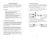
2.0 GENERAL INFORMATION Thank you for your purchase of this Patton Electronics product. This product has been thoroughly inspected and tested and is warranted for One Year parts and labor. If any questions arise during installation or use of the unit, contact Patton Electronics Technical Services at (301) 975-1007. 2.3 SUPPORTED APPLICATIONS The Model 2715 provides an E1 network termination between E1 and Fractional E1 equipment and customer premises equipment (CPE) such as a router.
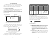
3.0 CONFIGURATION The Model 2715 features configuration capability via hardware switches or a software control port. This section describes all possible hardware and software switch configurations of the Model 2715. 3.1 DIP SWITCH CONFIGURATION The Model 2715 has eight internal DIP switches that allow configuration for a wide range of applications. The eight switches are accessed by opening the plastic case with a small screwdriver.
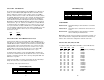
Switch SW2: CAS Multiframe UNFRAMED (G.703) The Channel Associated Signaling (CAS) multiframe uses Timeslot 16 (TS16) to send multiframe (MF) alignment data. In CAS MF, a multiframe is defined as 16 frames, where a frame consists of 32 64kb/s timeslots, numbered 0 to 31. TS16 of the first frame in the MF contains the CAS MF alignment word in the upper four bits. The alignment word is always 0000 (binary).
NOTE: When the data rate is set to 2.048Mb/s, then the unit is forced into G.703 mode, and it transmits user data on all 32 timeslots. There is no framing information; therefore, the CAS MF (SW2)and CRC-4 (SW3) switches are ignored. In all other rate settings, the unit employs G.704 framing; TS0 is reserved for signaling. 3.2 SOFTWARE CONFIGURATION The Model 2715 features a menu-driven command system that allows you to monitor/configure its operating parameters.
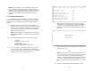
3.2.1 Introduction to Main Menu The Main Menu options are briefly described below. After entering the password, you may access all of the system’s functions and parameters. The Main Menu looks like this: a System Configuration options allow you to change various aspects of the Model 2715’s operation, e.g., framing, line coding, and aggregate bandwidth. b System Diagnostics/Statistics options allow you to monitor the network performance, initiate V.54 loops, local loops, and send test patterns.
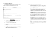
b 3.2.2 System Configuration The System Configuration menu looks like this: Line Coding: HDB3 (default) Options: AMI, HDB3 HDB3: In this line coding, the transmitter substitutes a deliberate bipolar violation when excessive zeros in the data stream are detected. The receiver recognizes these special violations and decodes them as zeros. This method enables the network to meet minimum pulse density requirements. Unless AMI is required in your application, HDB3 should be used whenever possible.
d Clocking: Network (default) g Options: Network, Internal, External Options: Enabled, Disabled Network: This is the most commonly used setting when connecting to a carrier’s network. In this mode, the unit recovers the clock from the received signal and uses it to transmit data. In this way the unit remains synchronized to a master clock. In campus applications, one of the units must be set to Internal clock, and the other end is set to Network clock. At all times, there must be only one clock source.
If you do not have a terminal, you may force the unit to use the DIP switches as the default configuration source by turning off the unit, setting all the DIP switches to the ON position, then powering on the unit. This will cause the unit to enter a special mode. Then turn off the unit and change the switch settings to the desired settings. When you turn the unit on again, the unit will be set up with the selected switch settings. n 3.2.
b Remote Loop Idle (default) The Model 2715 receiving a RL can be in one of the following states: The Remote Digital Loopback (RDL) test checks the performance of both the local and remote Model 2715s, as well as the communication link between them. Data from the local DTE is sent across the entire communication circuit and looped back to the local DTE. RxPr The Model 2715 is receiving a preparatory pattern. Sack The Model 2715, upon receiving a preparatory pattern, sends an acknowledgement message.
Use this option to select the test pattern used to test the link. 3.2.4 Unit Options NI STATUS The Unit Options screen looks like this (factory default): The Network interface (NI) status is shown in the middle of the Diagnostics/Statistics screen. The brackets are empty when the link is operating normally. Only one error message is provided RCL Receiver Carrier Loss [RCL] occurs when 255 consecutive zeros have been detected at the network interface. RCL clears when a pulse is detected.
4.0 INSTALLATION d Loop Timeout The Loop Timeout setting can be set to one of the following: 00:05 = 00:10 = 00:15 = 00:30 = 00:45 = 01:00 = 01:30 = 02:00 = 03:00 = NEVER = f five minutes ten minutes fifteen minutes thirty minutes (default setting) forty-five minutes one hour 90 minutes two hours three hours forever—the unit will remain in loopback without user intervention. The Model 2715 is equipped with DTE, network, and power interfaces. This section briefly describes connection to each. 4.
5.0 OPERATION 4.3 POWER CONNECTION The Model 2715 offers three ways to supply external power: AC power, DC power and interface power. Once the Model 2715 is installed and configured properly it is ready to place into operation. This section describes the function of the LED indicators, and the use of the loopback and pattern test modes. 4.3.1 Using the AC Power Supply (100-240VAC) 5.1 LED DESCRIPTIONS The Model 2715 uses a 5VDC, 2A universal input 100-240VAC, power supply (center pin is +5V).
LOS ALM The Loss of Sync LED lights when the unit loses synchronization with the incoming signal. This may happen when there is a framing mismatch or a loss of signal. In unframed mode, the LOS LED monitors the status of the transmit clock. The alarm LED indicates the presence of a AIS or RAI, or Out of Frame condition. The ALM LED will blink on every half-second. Alarms may occur due to: • Loss of Synchronization • Loss of Frame • AIS (Blue Alarm) • RAI (Yellow Alarm) 5.2 LOOP (V.
To perform an RDL test, follow these steps: 1. Activate RDL. This may be done in two ways: a. b. 2. Enter b Remote Loop from the System Diagnostics/Statistics menu and toggle the until “TM” appears next to the b Remote Loop option.; Activate the “RL” signal on the DTE. If you are not sure which lead is the “RL” signal, please refer to Appendix D. Perform a bit error rate test (BERT) using the internal V.52 generator (as described in Section 5.3), or using a separate BER Tester.
APPENDIX A APPENDIX B PATTON MODEL 2715 PATTON MODEL 2715 SPECIFICATIONS CABLE RECOMMENDATIONS Network Data Rate: 2.048 Mbps Network Connector: RJ-48C Nominal Impedance: 120 ohm (75 ohm available when using Patton Model 460 Balun) DTE Interface: V.35 (DCE Orientation) on Male M/34 Line Coding: Selectable AMI or HDB3 Line Framing: G.703 (Unframed) or G.704/G.
APPENDIX C APPENDIX D PATTON MODEL 2715 PATTON MODEL 2715 FACTORY REPLACEMENT PARTS AND ACCESSORIES INTERFACE PIN ASSIGNMENTS RJ-48C E1 Network Interface (RJ-48S Female Modular Jack) Description Patton Model # 2715/CM/UI .....................V.35 to E1 Converter (V.35 M/34 Male, UI) 10 - 09F...........................6 Foot Control Port Cable, 25 mm to DB9F 08055DCUI......................
APPENDIX D APPENDIX E (continued) PATTON MODEL 2715 PATTON MODEL 2715 POWER SUPPLY INTERFACE INTERFACE PIN ASSIGNMENTS M/34 Connector, Terminal Interface Pin # A B D E F L M N P R S T U V W X Y AA KK Signal GND (Earth Ground/Shield) SGND (Signal Ground) CTS (DCE Source) DSR (DCE Source, Always On) CD (DCE Source) LL (Local Loop, DTE Source) TM (Test Mode Indicator (DCE Source) RL (Remote Loop, DTE Source) TD (Transmit Data +, DTE Source) RD (Receive Data +, DCE Source) TD/ (Transmit Data -, DTE Sourc
Copyright © 2006 Patton Electronics Company All Rights Reserved.