USER MANUAL MODEL 2124/2130 Ethernet MicroBridge Part# 07M2124-UM Doc# 08306U2-001, Rev.
TABLE OF CONTENTS 1.0 1.1 1.2 1.3 Warranty Information ................................................................. Radio and TV Interference............................................................ CE Notice...................................................................................... Service.......................................................................................... 2.0 2.1 2.2 General Information....................................................................
1.0 WARRANTY INFORMATION Patton Electronics warrants all Model 2124/2130 components to be free from defects, and will—at our option—repair or replace the product should it fail within one year from the first date of shipment. This warranty is limited to defects in workmanship or materials, and does not cover customer damage, abuse or unauthorized modification. If this product fails or does not perform as warranted, your sole recourse shall be repair or replacement as described above.
1.2 CE NOTICE The CE symbol on your Patton Electronics equipment indicates that it is in compliance with the Electromagnetic Compatibility (EMC) directive and the Low Voltage Directive (LVD) of the Union European (EU). A Certificate of Compliance is available by contacting Patton Technical Support. 1.3 SERVICE All warranty and non-warranty repairs must be returned freight prepaid and insured to Patton Electronics.
2.0 GENERAL INFORMATION Thank you for your purchase of this Patton Electronics product. This product has been thoroughly inspected and tested and is warranted for One Year parts and labor. If any questions or problems arise during installation or use of this product, please do not hesitate to contact Patton Electronics Technical Support at (301) 975-1007. 2.1 FEATURES • Integral V.
3.0 PPP OPERATIONAL BACKGROUND PPP is a protocol used for multi-plexed transport over a point-to-point link. PPP operates on all full duplex media, and is a symmetric peer-topeer protocol, which can be broken into three main components: 1. A standard method to encapsulate datagrams over serial links; 2. A Link Control Protocol (LCP) to establish, configure, and test the data-link connection; 3. A family of Network Control Protocols (NCPs) to establish and configure different network layer protocols.
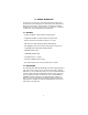
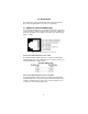
Figure 1. Cisco router with serial interface, configured as PPP Half Bridge. For example, the customer site is assigned the addresses 192.168.1.0/ 24 through 192.168.1.1/24. The address 192.168.1.1/24 is also the default gateway for the remote network. The above settings remove any routing/forwarding intelligence from the CPE. The associated Cisco configuration will set serial interface (s0) to accommodate half bridging for the above example. Authentication is optional under PPP.
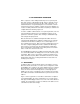
Figure 2. Transparent bridging between two routers over a serial link.
4.0 INSTALLATION The 2124/2130 is equipped with Network, DTE, and power interfaces. This section briefly describes connnection to each interface. 4.1 CONNECT TO 10BASET ETHERNET PORT The shielded RJ-45 Ethernet port on the Model 2124/2130 is designed to connect directly to a 10BaseT network. Figure 3 shows the 10BaseT RJ45 port pin description. You may make connections up to 300 feet using type 4 or 5 cable. Figure 3.
4.2 POWER CONNECTION The Model 2124/2130 offers either an AC or DC power supply. The 2124/2130 provides a strap selectable power supply. AC Power Supply (100-240VAC) The Model 2124/2130 uses a 5VDC, 2A universal input 100-240VAC, power supply (center pin is +5V). The universal input power supply is equipped with a male IEC-320 connector. This power supply connects to the Model 2124/2130 via a barrel jack on the rear panel. A variety of international power cords are available for the universal power supply.
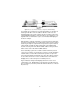
DC Power Figure 4. Strap positions 7 and 8 on J3 Supply DC power directly to the power supply jack. DC power supplied must be +5VDC ±5%, 500mA minimum, center positive, and can be supplied via a barrel type plug with 2.1/5.5/10mm I.D./O.D./Shaft Length dimensions. For this powering option, set J3 to position 7 and 8 as shown in figure 4 (factory default). The 36-60 VDC DC to DC adapter is supplied with the DC version of the Model 2124/2130.
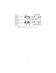
WARNING There are no user-serviceable parts in the power supply section of the Model 2124/2130. For more information, please contact Patton Electronics Technical support at (301) 975-1007, via our web site at http://www.patton.com, or by e-mail at support@patton.com. Power-up 2124 via DB-25 Connector on Pin 25 Place strap position 1 and 2 on J3 for DC power supply. See Figure 6 below. Power-up 2130 via DB-25 Connector on Pin 25 Place strap position 1 and 2 on J3 for DC power supply. See Figure 6 below.
Figure 7.
5.0 CONFIGURATION All configuration is done through software auto-detection for the Model 2124/2130. Once you have configured your mux or other equipment to be connected to the 2124/2130, the unit is ready for operation. Observe that the serial port of the 2124/2130 is configured as a DTE and must connect to a DCE. The LAN port also requires no configuration to connect to a 10BaseT Ethernet. Note The V.24 and EIA-530 Interface is configured as a DTE.
LED Descriptions Figure 8. 2124/2130 rear view The status LED blinks yellow from one to eleven times to indicate system status. Each pulse pattern is separated by a 2 second "off " period. Greater pulse patterns have higher priority (buffer saturation has greater priority than an empty MAC table).
Figure 9. Front of Model 2124/2130, showing LED indicators TXD- Trasmit data LED (green) blinks to indicate data transitions and remains OFF when no data is transmitted (idle). RXD- Received data LED (green) blinks to indicate data transitions and remains OFF when no data is received (idle). DTR- Control LED (yellow)- turns ON at power up to indicate to the DCE that the 2124 is active. CTS- Indication LED (yellow) - turns ON when the 2124 is ready to receive data from the DCE.
APPENDIX A PATTON ELECTRONICS MODEL 2124 SPECIFICATIONS LAN Connection: DTE connection: Protocol: MAC Address Table Size: MAC Address Aging: On-board Memory: Frame Latency: LEDs LAN Side: LEDs DTE Side: Power supply Input: Power Consumption: Humidity: Temperature: Dimensions: Compliance: RJ-45, 10BaseT, 802.3 Ethernet supported by Transparent LAN bridging DB-25 connector, V.
APPENDIX B PATTON ELECTRONICS MODEL 2130 SPECIFICATIONS LAN Connection: DTE connection: Protocol: MAC Address Table Size: MAC Address Aging: On-board Memory: Frame Latency: LEDs LAN Side: LEDs DTE Side: Power supply Input: Power Consumption: Humidity: Temperature: Dimensions: Compliance: RJ-45, 10BaseT, 802.
APPENDIX C 2124/2130 FACTORY REPLACEMENT PARTS Part # 07M2121/2135C 0805DCUI Description 2124/2130 User Manual 100-250 VAC Universal Power Supply 18
APPENDIX D 10BASET INTERFACE PIN ASSIGNMENT (RJ-45 FEMALE CONNECTOR) (DTE CONFIGURATION) Pin # 1 TD + 2 TD 3 RD + 4 5 6 RD 7 8 Signal (data output from 2124/2130) (data output from 2124/2130) (data input to 2124/2130) no connection no connection (data input to 2124/2130) no connection no connection 19
APPENDIX E V.
APPENDIX F EIA-530 TERMINAL INTERFACE PIN ASSIGNMENT (DB-25 MALE CONNECTOR) Pin# 1 2 3 4 5 7 8 9 10 12 13 14 15 16 17 19 20 21 23 25 Signal Shield GND/Frame GND TD A RD A RTS A CTS A SIG GND CD A RCV CLK B CD B TX CLK B CTS B TD B TX CLK A RD B RCV CLK A RTS B DTR A +5VDC DTR B +5VDC 21
APPENDIX G POWER SUPPLY INTERFACE Via 5VDC power jack (J1) Center Pin: +5VDC @ 500 mA minimun Outer Barrel: Ground 22
Notes _________________________________________________________ _________________________________________________________ _________________________________________________________ _________________________________________________________ _________________________________________________________ _________________________________________________________ _________________________________________________________ _________________________________________________________ __________________________________________