Model 2960/2996 Remote Access Server (RAS) User Manual Sales Office: +1 (301) 975-1000 Technical Support: +1 (301) 975-1007 E-mail: support@patton.com WWW: www.patton.com Part Number: 07MD2960-GS, Rev.
Patton Electronics Company, Inc. 7622 Rickenbacker Drive Gaithersburg, MD 20879 USA tel: +1 (301) 975-1000 fax: +1 (301) 869-9293 support: +1 (301) 975-1007 url: www.patton.com e-mail: support@patton.com Copyright Copyright © 2012, Patton Electronics Company. All rights reserved. Notice The information in this document is subject to change without notice. Patton Electronics assumes no liability for errors that may appear in this document.
Contents Compliance Information.......................................................................................................................................6 Radio and TV Interference ..................................................................................................................................... 6 Industry Canada Notice.......................................................................................................................................... 6 FCC Information ...
Model 2960/2996 RAS User Manual Contents Connecting the Ethernet ports ........................................................................................................................23 Connecting the 10/100Base-T Ethernet port to an Ethernet switch or hub ...............................................23 Connecting the 10/100Base-T Ethernet port to an Ethernet-capable workstation .....................................24 Connecting the EIA-561 RS-232 configuration port .............................
Model 2960/2996 RAS User Manual Contents Installing the replacement RAS .................................................................................................................58 Verifying the hardware installation ............................................................................................................58 Importing a saved configuration ................................................................................................................
Compliance Information Radio and TV Interference The Model 2900 Series generates and uses radio frequency energy, and if not installed and used properly—that is, in strict accordance with the manufacturer's instructions—may cause interference to radio and television reception.
Model 2960/2996 RAS User Manual Compliance Information work until the problem has been corrected or until you are certain that the Model 2900 Series is not malfunctioning. In accordance with FCC rules and regulation CFR 47 68.218(b)(6), you must notify the telephone company prior to disconnection. The following information may be required when applying to your local telephone company for leased line facilities. The Universal Service Order Code (USOC) is RJ48.
About this guide This guide describes installing and configuring a Patton Electronics Model 2960/2996 Remote Access Server (RAS). By the time you are finished with this guide, your RAS will be receiving calls and transferring data. The instructions in this guide are based on the following assumptions: • The RAS will connect to a T1, E1, or PRI line • Callers will dial-in and connect with a V.90/K56Flex/V.
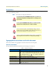
Model 2960/2996 RAS User Manual About this guide Precautions Notes and cautions, which have the following meanings, are used throughout this guide to help you become aware of potential RAS problems: Note Calls attention to important information. The shock hazard symbol and WARNING heading indicate a potential electric shock hazard. Strictly follow the warning instructions to avoid injury caused by electric shock. The alert symbol and WARNING heading indicate a potential safety hazard.
Model 2960/2996 RAS User Manual About this guide Table 1. General conventions (Continued) Convention Meaning Are you ready? All system messages and prompts appear in the Courier font as the system would display them. % dir *.* Bold Courier font indicates where the operator must type a response or command Mouse conventions The following conventions are used when describing mouse actions: Table 2.
Chapter 1 Introduction Chapter contents Model 2960/2996 Remote Access Server overview ................................................................................................12 Hardware overview ................................................................................................................................................13 WAN ............................................................................................................................................................
Model 2960/2996 RAS User Manual 1 • Introduction Model 2960/2996 Remote Access Server overview The Model 2960/2996 is a central site remote access server with integrated modems which terminate dial-up analog and digital users. The Model 2960 RAS combines 16, 24, 30, 48, 60 or 72 ports—the 2996 RAS combines 96 or 120—analog and digital modems, RAS software, a 10/100 Ethernet port, IP Routing, Frame Relay/PPP forwarding, and four T1/E1 WAN ports.
Model 2960/2996 RAS User Manual 1 • Introduction Hardware overview The Model 2960/2996 RAS is a fully integrated remote access server for central site concentration of analog and digital modem calls. The RAS (see figure 2) comprises a 1U-high 17-inch wide chassis that contains a motherboard and two dual-redundant power supplies. A full set of LEDs are present on the chassis front panel, while connections for WAN, LAN, and control ports are present on the rear of the chassis.
Model 2960/2996 RAS User Manual 1 • Introduction Signaling Robbed-bit, R1, R2, Q.921/Q.931 Modems Up to 48/60 (Model 2960) or 96/120 (Model 2996) V.92, V.90, K56Flex, V.34+, ISDN B-channel digital calls (additional ports/functionality can be added by installing optional PMC expansion modules), or 64 kbps and 56 kbps DOVBS (data over voice bearer services). RS-232 control port An RS-232 port provides for initial configuration of the RAS. The RS-232 port also supports: • Asynchronous data at 19.
Model 2960/2996 RAS User Manual 1 • Introduction Physical dimensions Weight: 8.94 lbs (20.12 kg) Refer to figure 3 for height, width, and depth dimensions. Figure 3.
Model 2960/2996 RAS User Manual 1 • Introduction • SNMP version 1 configuration management • Support for MIB-II (RFC-1213), DS1 MIB (RFC-1406), RIPv2 MIB (RFC 1389), Ethernet MIB (RFC1643), Frame Relay DTE MIB (RFC-1315) and Patton’s enterprise MIB (1768) • System logging to configuration port, non-volatile FLASH, volatile RAM, SYSLOG Daemon, and SNMP trap • RADIUS Accounting • Dial-in dynamic IP address pool management • User configurable login prompts and banners • Status reporting of all access server
Model 2960/2996 RAS User Manual 1 • Introduction • SYSTEM: Green if the RAS is operating normally. • ETHERNET: Green if link status is nominal for the Ethernet port. • CALLS ACT: Green to indicate call activity on the Model 2960/2996. • WAN STATUS: Green indicates normal status at each of the four T1/E1/PRI links. Red indicates an error.
Model 2960/2996 RAS User Manual 1 • Introduction Software overview The Patton Model 2960/2996 supports all common remote access services as well as integrated routing and forwarding (see table 3). Authentication and network management offer control and detailed monitoring from any web browser. From the PSTN, the Model 2960/2996 RAS will accept either T1/E1 or PRI connections, with support for both channel associated or common channel signaling. Table 3.
Chapter 2 Hardware installation Chapter contents Introduction ..........................................................................................................................................................20 Unpacking the Model 2960/2996 RAS .................................................................................................................20 RAS chassis installation.....................................................................................................................
Model 2960/2996 RAS User Manual 2 • Hardware installation Introduction This chapter contains the following procedures for installing the Model 2960/2996 RAS: • “Unpacking the Model 2960/2996 RAS”—lists the contents of the RAS shipping container • “RAS chassis installation”—describes installing the RAS on a flat surface or in a standard 19–inch rack.
Model 2960/2996 RAS User Manual 2 • Hardware installation Cable installation This section describes installing the power, ground, and network interface cables. Attaching the cable retainer clip To secure the power cord, it is necessary to attach the metal retainer clips (if applicable to your model). Squeeze the clip and insert into the holes in the screws on either side of the power connector on your unit. The clip will pop into place. Power cable retainer clip Figure 5.
Model 2960/2996 RAS User Manual 2 • Hardware installation 2. Rotate the power cable retainer clip so it secures the power cable plug in the IEC-320 connector as shown in figure 7. 0 /10 10 U N IT E D Q IS U C IP O P N E B N D E E W F C IT O T R B H E O D S T U E H A R S L V U S IC P U IN P P G LIE PL S IES ET RN HE ET Grounding stud Power cable retainer clip V 64 ) -2 Hz 90-60 P 0 (5 AM 2 Figure 7. Power cable retainer clip 3. Repeat steps 1 and 2 to install the remaining power cable.
Model 2960/2996 RAS User Manual 2 • Hardware installation Connecting the Ethernet ports The RAS has a single 10/100 Ethernet interface for connection to your LAN (see figure 8). The Ethernet port will autosense the correct speed of the local LAN and automatically negotiate half- or full-duplex operation. This section describes connecting the RAS to the Ethernet LAN via an Ethernet hub, switch, or workstation.
Model 2960/2996 RAS User Manual 2 • Hardware installation Connecting the 10/100Base-T Ethernet port to an Ethernet-capable workstation The 10/100Base-T Ethernet port can connect to a single Ethernet-capable workstation by means of a crossover cable. Refer to figure 10 to assemble a cross-connect cable that will connect between the NIC Ethernet port in the workstation and the RAS 10/100Base-T Ethernet port. 10Base-T Workstation RJ-45 Pin No. RAS 10/100Base-T Port RJ-45 Pin No.
Model 2960/2996 RAS User Manual 2 • Hardware installation 1. Refer to figure 12 for the T1/E1/PRI RJ-48C pinout diagram. Figure 12. T1/E1/PRI RJ-48C pinout diagram 2. Attach the network cable from the telephone network demarc to the Primary T1/E1/PRI port (RJ-48C) on the RAS. Note For 75-ohm twin-coax E1 connections, use the Patton Model 460 E1 120-ohm/75-ohm adapter to convert from a 75-ohm dual-coax to the 120-ohm twisted-pair interface the RAS uses.
Chapter 3 Configuring the RAS for operation Chapter contents Introduction ..........................................................................................................................................................27 Configuration prerequisites ...................................................................................................................................27 Preparing the RAS for configuration..................................................................................
Model 2960/2996 RAS User Manual 3 • Configuring the RAS for operation Introduction This chapter contains the following procedures for configuring the Model 2960/2996 Remote Access Server for operation: • “Configuration prerequisites”—lists the items you need to have on hand before configuring the RAS. • “Preparing the RAS for configuration”—describes setting up the RAS IP address and netmask parameters.
Model 2960/2996 RAS User Manual 3 • Configuring the RAS for operation – 8 bits – No Parity – 1 Stop bit – No flow control 3. Set up HyperTerminal™ as follows: – Open a HyperTerminal session. – Enter a name for this connection. – Click on the Connect using: pop-up menu and choose the Direct to ComX option (where X is the number of the COM port onto which you connected the cable in step 1) (see figure 13). Figure 13. Hyperterminal properties – Configure the COM port settings as shown in figure 14.
Model 2960/2996 RAS User Manual 3 • Configuring the RAS for operation Figure 14. COM properties Figure 15. Terminal keys configuration – Configure the Settings for Function, arrow and ctrl keys act as to Terminal keys as shown in figure 15. 4. Press to display the login window, which will resemble that shown in figure 16.
Model 2960/2996 RAS User Manual 3 • Configuring the RAS for operation Figure 16. Login window 5. Type superuser as the default username and password, then press . The Top Level Management window displays (see figure 17). Figure 17. VT-100 Top Level Management window 6. Select option g Ethernet. 7. Select a PrimaryIpAddress to set the Ethernet IP address. 8. Type the IP address at the > prompt, then press . 9. Use the left arrow key to return to the previous menu. 10.
Model 2960/2996 RAS User Manual Note 3 • Configuring the RAS for operation The default gateway has not been configured at this time. You can access the web pages with a PC located on the same network as the RAS or you must configure the default gateway using HyperTerminal. Select k IP then 2 Default Gateway.
Model 2960/2996 RAS User Manual 3 • Configuring the RAS for operation Home page overview The HOME window is divided into two panes: the Configuration Menu pane and the configuration/information pane (see figure 19). The Configuration Menu contains the links to the various RAS subsystems, while the configuration/information pane is where you can view status and other information, or make changes to the system configuration.
Model 2960/2996 RAS User Manual 3 • Configuring the RAS for operation From the Home page, the following actions can be performed: • Record Current Configuration—clicking on this button (figure 20) causes the current configuration to be stored in FLASH memory. Any changes made to the RAS configuration are stored in non-volatile RAM first. This allows the user to set the box up with a working configuration before committing it to FLASH.
Model 2960/2996 RAS User Manual 3 • Configuring the RAS for operation Configuring simple authentication The following sections describe two methods for configuring simple authentication to test the setup. No Validation A No Validation authentication setting means that the user will be able to log in without requiring a username or password. 1. Select Authentication on the Configuration Menu. The Authentication window displays (see figure 21). Figure 21.
Model 2960/2996 RAS User Manual 3 • Configuring the RAS for operation Figure 22. Authentication Configuration window 2. Click on Modify. The Authentication Configuration window appears (see figure 22). 3. Change Validation to noValidation(0). 4. Click on the Submit Query button. A Static User The Static User authentication setting means that the user will have to use the static username and password you create to log in. 1. Select Authentication on the Configuration Menu.
Model 2960/2996 RAS User Manual 3 • Configuring the RAS for operation 3. Add the desired username and password. 4. Click on the Submit Query button. 5. Click on Modify. The Authentication Configuration window appears (see figure 22 on page 35). 6. Change Validation to StaticUsers(1). 7. Click on the Submit Query button. Note Static Users or RADIUS are not used if validation is set to noValidation(0). Configuring dial-in user information 1. Click on Dial-in in the Configuration Menu.
Model 2960/2996 RAS User Manual 3 • Configuring the RAS for operation 2. Click on Modify. The Modify Dial-In window appears (see figure 25). Figure 25. Modify Dial-In window, Login section 3. The IP address pool contains the IP addresses that are assigned dynamically to the dial-in connections. Type the IP address pool in the space provided.
Model 2960/2996 RAS User Manual 3 • Configuring the RAS for operation Figure 26. Modify Dial-In window, Domain Name Server section 6. Enter in the IP Address of the primary and secondary domain name servers (DNS). The DNS enables users to find locations on the Internet. 7. Click on Submit Query. Configuring the default gateway Do the following to add the default gateway (if it was not already configured through HyperTerminal): 1.
Model 2960/2996 RAS User Manual 3 • Configuring the RAS for operation Configuring line settings and signaling for E1 1. Select T1/E1 Link on the Configuration Menu. The T1/E1 Link Activity window appears (see figure 28). Figure 28. T1/E1 Link Activity window 2. Link: 1 corresponds to Line 1 on the RAS. This is the primary link for dial-in callers. Under Link 1, Click on Configuration then Modify. The Line Interface Settings section of the WAN Circuit Configuration window appears (see figure 29).
Model 2960/2996 RAS User Manual 3 • Configuring the RAS for operation Configuring the line settings 1. Click on the Line Type pop-up menu (see figure 29 on page 39) and choose from the following options: – For an E1/PRI line your options will be either dsx1E1(4) or dsx1E1-CRC(5) – For an E1/R2 line your options will be either dsx1E1-MF(6) or dsx1E1-CRC-MF(7) 2. Click on the Line Coding pop-up menu (see figure 29 on page 39) and choose either dsx1AMI(5) or dsxHDB3(3). Most installations will use HDB3. 3.
Model 2960/2996 RAS User Manual 3 • Configuring the RAS for operation Figure 31. WAN Circuit Configuration window, signaling Settings section Setting the line signaling for an E1/PRI (ISDN) line Do the following: 1. Scroll down the WAN Circuit Configuration window, until the Signaling Settings section appears (see figure 31). 2. Click on the Signal Mode pop-up menu and choose messageOriented(4). 3. Click on the Message Oriented Switch Type pop-up menu (see figure 31) and choose CTR4(3). 4.
Model 2960/2996 RAS User Manual 3 • Configuring the RAS for operation Figure 32. MFR Version 2 Modify window 5. Click on the Country pop-up menu. If your country is not available, select ituStandard(1). 6. Click on Submit. 7. Scroll down to the Interregister signaling section. 8. Type the Called Number Total Digits in the box provided. This setting tells the RAS how many digits to expect from the phone company. The called Number is the number a user dials to call into the RAS. 9.
Model 2960/2996 RAS User Manual Note 3 • Configuring the RAS for operation The information entered into the Interregister Signaling section must match the information the telco provided. If the information entered is not the same, the RAS may not answer calls. In some installations, the phone company will send a special tone to alert that it is done sending the Calling Number. In this case, the value in the Total Digits box does not have to match the telephone company’s exactly.
Model 2960/2996 RAS User Manual 3 • Configuring the RAS for operation – dsx1D4 AT&T D4 format DS1 – For ISDN PRI service, set the line type to dsx1ESF 2. Click on the Line Coding pop-up menu (see figure 29 on page 39). The most common options are: dsx1B8ZS and dsx1AMI. For ISDN PRI service, set the line coding to dsx1B8ZS. 3. Click on the Line Build Out pop-up menu (see figure 29 on page 39) and select t1pulse0dB(1). 4. Click on the Yellow Alarm Format pop-up menu and choose linkYellowFormatBit2(1). 5.
Model 2960/2996 RAS User Manual 3 • Configuring the RAS for operation – For T1 lines with ESF/B8ZS this should be set to linkYellowFormatDL(2). 7. Click on Submit Query. Channel assignment This section describes configuring the RAS so it will know which channels are active. Do the following: 1. Select T1/E1 Link on the Configuration Menu. The T1/E1 Link Activity window appears (see figure 28 on page 39). 2. Click on Channel Assignment.
Model 2960/2996 RAS User Manual 3 • Configuring the RAS for operation 4. To import or export a configuration, click on Import/Export under the Configuration Menu to display the Import/Export main window (see figure 34). Figure 34. Import/Export main window 5. To export the flash configuration, click on the Export Flash link on the Import/Export main page. The access server will display text configuration information resembling that shown in figure 35. Figure 35.
Model 2960/2996 RAS User Manual 3 • Configuring the RAS for operation To save the displayed data as a text file, select the Save option on your browser (see figure 36). For example, under Netscape, select File > Save As. A dialog box will display enabling you to save the contents of the export parameters to a text file. Select the location where you want the file stored, type a file name, and click Save. Figure 36.
Model 2960/2996 RAS User Manual Note 3 • Configuring the RAS for operation If the RAS does not respond as described, the most likely cause is that the RAS default settings are not compatible with the T1/E1 line. If this is the case, use the RS-232 CONFIG port to correct the RAS settings. You will have to examine the T1/E1 Link section in the configuration pages in the RAS. 6.
Chapter 4 Operation and shutdown Chapter contents Introduction ..........................................................................................................................................................50 Activating the RAS ................................................................................................................................................50 De-activating the RAS ......................................................................................................
Model 2960/2996 RAS User Manual 4 • Operation and shutdown Introduction This chapter describes how to start or power-down the RAS. Activating the RAS Once the RAS has been installed, no operator action is required under normal conditions; the RAS is designed for unattended operation. The RAS does not have a power switch. When either power supply is connected to power, the RAS will immediately begin its boot-up cycle.
Chapter 5 Troubleshooting and maintenance Chapter contents Introduction ..........................................................................................................................................................52 Fault analysis .........................................................................................................................................................53 Periodic maintenance .........................................................................................
Model 2960/2996 RAS User Manual 5 • Troubleshooting and maintenance Introduction This chapter describes troubleshooting and fault analysis that can be performed by the operator. If you require more help, refer to Chapter 6, “Contacting Patton for assistance”. Refer to table 4 for a list of common symptoms and suggested remedies. Note The following information assumes that there is only one failure involving the RAS and that if you perform the corrective action listed, it will solve the problem.
Model 2960/2996 RAS User Manual 5 • Troubleshooting and maintenance Fault analysis The following procedures outline steps you should follow when troubleshooting a RAS malfunction. 1. If possible, talk to the person who filed the trouble complaint and determine the operational symptoms. Record the symptoms on the appropriate trouble report form (include the front panel LED indications). 2.
Model 2960/2996 RAS User Manual 5 • Troubleshooting and maintenance Table 5. LED definitions (Continued) LED ETHERNET Location Color Status Front panel Green Off Meaning • A valid link has not been detected. • Verify that the cable is plugged into the hub, switch, or workstation and the RAS. • Verify that the hub, switch, or workstation is powered on. Replace the cable. If the problem still exists, refer to “Replacing the RAS” on page 55 to replace the RAS.
Model 2960/2996 RAS User Manual 5 • Troubleshooting and maintenance Periodic maintenance Other than using a lint-free cloth to clean dust off the RAS chassis, the RAS requires no periodic maintenance. Calibration The RAS requires no calibration. Maintenance This section describes replacing the RAS.
Model 2960/2996 RAS User Manual Note 5 • Troubleshooting and maintenance The parameters that will be exported are the power-up settings as they are stored in flash memory and may not be the current operating parameters. To ensure that you export the most current parameters, go to HOME, then click on the Record Current Configuration button under Immediate Actions. 3. To export the flash configuration, click on the Export Flash link on the Import/Export main page.
Model 2960/2996 RAS User Manual 5 • Troubleshooting and maintenance 4. To save the displayed data as a text file, select the Save option on your browser (see figure 39). For example, under Netscape, select File > Save As. A dialog box will display enabling you to save the contents of the export parameters to a text file. Select the location where you want the file stored, type a file name, and click Save. Figure 39.
Model 2960/2996 RAS User Manual 5 • Troubleshooting and maintenance Installing the replacement RAS 1. If you are installing the replacement RAS in a 19-inch rack, go to step 2. Otherwise, place the RAS at the desired location, then go to step 5. 2. Install the rack mounting ears onto the RAS using the mounting hardware provided. 3. Place the RAS at the desired position in the rack. 4. Secure the RAS in position with the mounting screws. 5. Install the ground wire onto the grounding stud. 6.
Model 2960/2996 RAS User Manual 5 • Troubleshooting and maintenance 3. Set up HyperTerminal™ as follows: – Open a HyperTerminal session. – Enter a name for this connection. – Click on the Connect using: pop-up menu and choose the Direct to ComX option (where X is the number of the COM port onto which you connected the cable in step 1) (see figure 40). Figure 40. HyperTerminal properties – Configure the COM port settings as shown in figure 41. Figure 41.
Model 2960/2996 RAS User Manual 5 • Troubleshooting and maintenance – Configure the Settings for Function, arrow and ctrl keys act as to Terminal keys as shown in figure 42. Figure 42. Terminal keys configuration 4. Press to display the login window (see figure 43). Figure 43.
Model 2960/2996 RAS User Manual 5 • Troubleshooting and maintenance 5. Type superuser as the default username and password, then press . The Top Level Management window displays (see figure 44). Figure 44. VT-100 Top Level Management window 6. Select option g Ethernet. 7. Select a PrimaryIpAddress to set the Ethernet IP address. 8. Type the IP address at the > prompt, then press . 9. Use the left arrow key to return to the previous menu. 10.
Model 2960/2996 RAS User Manual Note 5 • Troubleshooting and maintenance Do not select Record Current Configuration after importing configuration parameters. Completing the installation This section verifies that the RAS is fully operational. 1. Temporarily disconnect the male ends of both power cords from the power distribution strip or to a wall outlet. Wait 30 seconds, then plug the power cords in again. 2. Verify that the green POWER LED is lit.
Chapter 6 Contacting Patton for assistance Chapter contents Introduction ..........................................................................................................................................................64 Contact information..............................................................................................................................................64 Warranty Service and Returned Merchandise Authorizations (RMAs).....................................................
Model 2960/2996 RAS User Manual 6 • Contacting Patton for assistance Introduction This chapter contains the following information: • “Contact information”—describes how to contact PATTON technical support for assistance. • “Warranty Service and Returned Merchandise Authorizations (RMAs)”—contains information about the RAS warranty and obtaining a return merchandise authorization (RMA). Contact information Patton Electronics offers a wide array of free technical services.
Model 2960/2996 RAS User Manual 6 • Contacting Patton for assistance Return for credit policy • Less than 30 days: No Charge. Your credit will be issued upon receipt and inspection of the equipment. • 30 to 60 days: We will add a 20% restocking charge (crediting your account with 80% of the purchase price). • Over 60 days: Products will be accepted for repairs only. RMA numbers RMA numbers are required for all product returns.