For Quick Start Installation SmartNode 4950-NCE Series Multi-Port T1/E1/PRI VoIP Enterprise Gateway Router Getting Started Guide Sales Office: +1 (301) 975-1000 Technical Support: +1 (301) 975-1007 E-mail: support@patton.com WWW: www.patton.com Part Number: 07MSN4950-NCE-GS, Rev.
Patton Electronics Company, Inc. 7622 Rickenbacker Drive Gaithersburg, MD 20879 USA Tel: +1 (301) 975-1000 Fax: +1 (301) 869-9293 Support: +1 (301) 975-1007 Web: www.patton.com E-mail: support@patton.com Trademark Statement The terms SmartNode and SmartWare are trademarks of Patton Electronics Company. All other trademarks presented in this document are the property of their respective owners. Copyright © 2008-2011, Patton Electronics Company. All rights reserved.
Summary Table of Contents 1 General information ...................................................................................................................................... 13 2 Applications overview.................................................................................................................................... 20 3 SmartNode installation..................................................................................................................................
Table of Contents Summary Table of Contents ........................................................................................................................... 3 Table of Contents ........................................................................................................................................... 4 List of Figures ................................................................................................................................................. 7 List of Tables ...
SmartNode 4950-NCE Getting Started Guide Table of Contents 1. Connecting the SmartNode to your laptop PC..................................................................................................28 2. Configuring the desired IP address ....................................................................................................................29 Factory-default IP settings ........................................................................................................................
SmartNode 4950-NCE Getting Started Guide Table of Contents Fax and modem support........................................................................................................................................47 Voice signalling .....................................................................................................................................................48 Voice routing—session router..............................................................................................
List of Figures 1 2 3 4 5 6 7 8 9 10 11 12 13 14 15 16 SmartNode 4950-NCE . . . . . . . . . . . . . . . . . . . . . . . . . . . . . . . . . . . . . . . . . . . . . . . . . . . . . . . . . . . . . . . . . . . 14 SN4950-NCE rear panel . . . . . . . . . . . . . . . . . . . . . . . . . . . . . . . . . . . . . . . . . . . . . . . . . . . . . . . . . . . . . . . . . 16 SmartNode 4950-NCE front panel . . . . . . . . . . . . . . . . . . . . . . . . . . . . . . . . . . . . . . . . . . . . . . . . . . . . . . . . .
List of Tables 1 2 3 4 5 6 7 8 9 10 11 12 13 14 15 16 17 General conventions . . . . . . . . . . . . . . . . . . . . . . . . . . . . . . . . . . . . . . . . . . . . . . . . . . . . . . . . . . . . . . . . . . . . . 12 SmartNode 4950-NCE PRI Ports and Voice Channels . . . . . . . . . . . . . . . . . . . . . . . . . . . . . . . . . . . . . . . . . . 15 SmartNode 4950-NCE models with integrated G.SHDSL interface . . . . . . . . . . . . . . . . . . . . . . . . . . . . . . . . 15 Rear panel ports . . . . . . .
About this guide This guide describes the SmartNode 4950-NCE hardware, installation and basic configuration. For detailed software configuration information refer to the SmartWare Software Configuration Guide and the available Configuration Notes.
SmartNode 4950-NCE Getting Started Guide Precautions Notes, cautions, and warnings, which have the following meanings, are used throughout this guide to help you become aware of potential problems. Warnings are intended to prevent safety hazards that could result in personal injury. Cautions are intended to prevent situations that could result in property damage or impaired functioning. Note A note presents additional information or interesting sidelights.
SmartNode 4950-NCE Getting Started Guide Safety when working with electricity • Do not open the device when the power cord is connected. For systems WARNING • • • • • • without a power switch and without an external power adapter, line voltages are present within the device when the power cord is connected.
SmartNode 4950-NCE Getting Started Guide Always follow ESD prevention procedures when removing and replacing cards. CAUTION Wear an ESD-preventive wrist strap, ensuring that it makes good skin contact. Connect the clip to an unpainted surface of the chassis frame to safely channel unwanted ESD voltages to ground. To properly guard against ESD damage and shocks, the wrist strap and cord must operate effectively. If no wrist strap is available, ground yourself by touching the metal part of the chassis.
Chapter 1 General information Chapter contents SmartNode 4950-NCE overview...........................................................................................................................14 SN4950-NCE model codes .............................................................................................................................15 SN4951-NCE model codes .............................................................................................................................
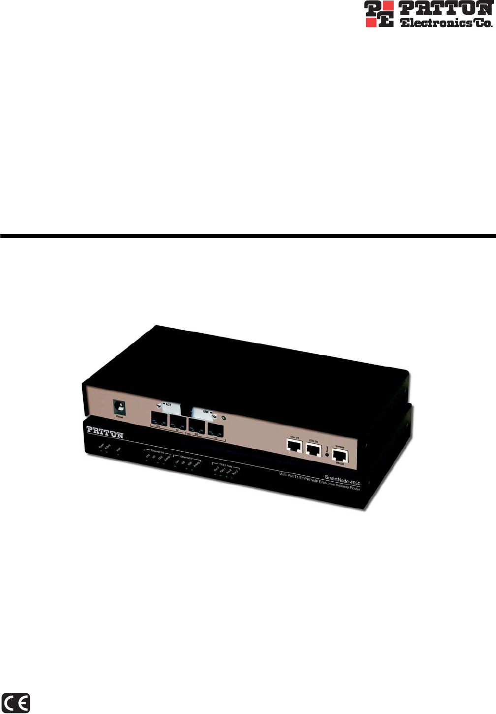
SmartNode 4950-NCE Getting Started Guide 1 • General information SmartNode 4950-NCE overview The SmartNode 4950-NCE T1/E1 PRI VoIP Router (see figure 1) combines Universal SIP Trunking, IP routing, VPN/Security, and Quality of Service with high-quality Voice over IP (VoIP) delivered on 1 to 4 Primary Rate Interfaces (PRI T1/E1). This combination paves the way for enterprises’ migration to unified communications by integrating legacy telephone systems with PSTN and VoIP networks. Figure 1.
SmartNode 4950-NCE Getting Started Guide 1 • General information SN4950-NCE model codes The SmartNode 4950-NCE series consists of several models. They differ in the number of PRI ports and voice channels supported. All models come equipped with two 10/100/1000Base-T Ethernet ports. The SmartNode 4950-NCE PRI ports and voice channels are listed in table 2. The SmartNode 4950-NCE G.SHDSL models are listed in table 3. Table 2.
SmartNode 4950-NCE Getting Started Guide 1 • General information SN4951-NCE model codes The high precision SmartNode 4951-NCE models have a Stratum III clock. The Stratum III clock provides a clock source of < 5 ppm. For PBXs that used to rely on PSTN for accurate clock source, the SmartNode 4951 can provide a PSTN-equivalent high precision clock. The popular DECT PBX needs such high precision clocks. Note For high precision clock models, replace SN4950-NCE with SN4951 in the model code.
SmartNode 4950-NCE Getting Started Guide 1 • General information Table 4. Rear panel ports Port Description WAN ETH 0/0 Auto-MDX Gigabit-Ethernet port, RJ-45 (see figure 2), connects the unit to an Ethernet WAN device (for example, a cable modem, DSL modem, or fiber modem). Note: Only full duplex modes are supported. LAN ETH 0/1 Auto-MDX Gigabit-Ethernet port, RJ-45 (see figure 2), connect the unit to an Ethernet LAN (for example, a PC, printer, or wireless bridge).
SmartNode 4950-NCE Getting Started Guide 1 • General information SmartNode 4950-NCE front panel Figure 3 shows SmartNode 4950-NCE front panel LEDs, the LED definitions are listed in table 5.
SmartNode 4950-NCE Getting Started Guide 1 • General information Table 5. SN4950-NCE Front and Rear panel LEDs LED Description Note If an error occurs, all LEDs will flash once per second. Power When lit, indicates power is applied. Run When lit, the unit is in normal operation. Flashes once per second during boot (startup). VoIP Link • On indicates the gateway is registered to an H.323 gatekeeper/SIP server, or, in the case of direct routing, has at least one active VoIP connection.
Chapter 2 Applications overview Chapter contents Introduction ..........................................................................................................................................................21 Application—Multi-service ISDN Internet telephony IAD ...................................................................................
SmartNode 4950-NCE Getting Started Guide 2 • Applications overview Introduction Patton’s SmartNode VoIP Media Gateway Routers deliver the features you need for advanced multiservice voice and data network applications. They combine high quality voice-over-IP with powerful quality of service routing functions to build professional and reliable VoIP and data networks. This chapter describes typical applications for which this SmartNode is uniquely suited.
Chapter 3 SmartNode installation Chapter contents Planning the installation........................................................................................................................................23 Site log ............................................................................................................................................................23 Network information ............................................................................................................
SmartNode 4950-NCE Getting Started Guide 3 • SmartNode installation Planning the installation Before installing the gateway router device, the following tasks should be completed: • Create a network diagram (see section “Network information” on page 23) • Gather IP related information (see section “IP related information” on page 23 for more information) • Install the hardware and software needed to configure the SmartNode.
SmartNode 4950-NCE Getting Started Guide 3 • SmartNode installation • IP addresses of central H.323 gatekeeper (if used) • IP addresses and/or URL of SIP servers or Internet telephony services (if used) • Login and password for PPPoE Access • Login and password for SIP or H.
SmartNode 4950-NCE Getting Started Guide 3 • SmartNode installation Connect the cables in the following order: CAUTION The interconnecting cables shall be acceptable for external use and shall be rated for the proper application with respect to voltage, current, anticipated temperature, flammability, and mechanical serviceability. 1. Connect the T1/E1 cables to the PRI T1/E1 ports (see Appendix C on page 53 and Appendix D on page 58). 2.
SmartNode 4950-NCE Getting Started Guide 3 • SmartNode installation Connecting the power supply • Do not connect power to the AC Mains at this time. WARNING CAUTION • The external power adapter shall be a listed Limited Power Source. • The 4950-NCE external power supply automatically adjusts to accept an input voltage from 100 to 240 VAC (50/60 Hz). Verify that the proper voltage is present before plugging the power cord into the receptacle. Failure to do so could result in equipment damage. 1.
Chapter 4 Initial configuration Chapter contents Introduction ..........................................................................................................................................................28 1. Connecting the SmartNode to your laptop PC..................................................................................................28 2. Configuring the desired IP address ...........................................................................................................
SmartNode 4950-NCE Getting Started Guide 4 • Initial configuration Introduction This chapter leads you through the basic steps to set up a new SmartNode and to download a configuration. Setting up a new SmartNode consists of the following main steps: Note If you haven’t already installed the SmartNode, refer to chapter 3, “SmartNode installation” on page 22.
SmartNode 4950-NCE Getting Started Guide 4 • Initial configuration 2. Configuring the desired IP address Factory-default IP settings The factory default configuration for the Ethernet interface IP addresses and network masks are listed in table 7. Both Ethernet interfaces are activated upon power-up. LAN interface ETH 0/1 (LAN) provides a default DHCP server, the WAN interface uses DHCP client to automatically assign the IP address and network mask. Table 7.
SmartNode 4950-NCE Getting Started Guide 4 • Initial configuration Now you can set your IP address and network mask for the interface ETH 0/0 (WAN). Within this example a network 172.16.1.0/24 address is assumed. The IP address in this example is set to 172.16.1.99 (you should set this the IP address given to you by your network provider). 192.168.1.1(ctx-ip)[router]#interface WAN 192.168.1.1(if-ip)[WAN]#ipaddress 172.16.1.99 255.255.255.0 2002-10-29T00:09:40 : LOGINFO : Link down on interface WAN.
SmartNode 4950-NCE Getting Started Guide 4 • Initial configuration You can check the connection with the ping command from the SmartNode to another host on the network. 172.16.1.99(if-ip)[WAN]#ping Note If the WAN address is not set to DHCP, to ping a device outside your local LAN you must first configure the default gateway.
SmartNode 4950-NCE Getting Started Guide 4 • Initial configuration 172.16.1.99(if-ip)[WAN]#reload Running configuration has been changed. Do you want to copy the 'running-config' to the 'startup-config'? Press 'yes' to store, 'no' to drop changes : no Press 'yes' to restart, 'no' to cancel : yes The system is going down Bootloader The bootloader ensures that basic operations, network access, and downloads are possible in case of interrupted or corrupted application image downloads.
SmartNode 4950-NCE Getting Started Guide Step 4 • Initial configuration Command Purpose 2 RedBoot> ip_address -g gateway optional Sets the IP address of the default gateway. 3 RedBoot> ping -h tftp-server_ip_address optional Tests the connectivity to the TFTP server. 4 RedBoot> load -r -v -h host -b base_address file_name Downloads an application image into the volatile memory (RAM) from where the SmartNode could directly execute it.
SmartNode 4950-NCE Getting Started Guide 4 • Initial configuration Using default protocol (TFTP) Raw file loaded 0x01800100-0x0199ca6b, 1689964 bytes, assumed entry at 0x01800100 RedBoot> fis delete -n 1 Delete image 1 - continue (y/n)? y ... Erase from 0x60030000-0x601cc974: .......................... RedBoot> fis create Use address 0x01800100, size 1684402 ? - continue (y/n)? y ... Erase from 0x60030000-0x601cb3ba: .......................... ... Program from 0x00011eec-0x00011ef4 at 0x60030000: . ...
SmartNode 4950-NCE Getting Started Guide Step 8 Command RedBoot> go Note 4 • Initial configuration Purpose Starts the application image that was downloaded to the volatile memory (RAM). This type of download takes about 25 minutes since it uses a serial link at only 9600 bps. Additional information For detailed information about configuring and operating guidance, set up procedures, and troubleshooting, refer to the SmartNode Series SmartWare Software Configuration Guide on the CD-ROM.
Chapter 5 G.SHDSL Basic Configuration Chapter contents Introduction ..........................................................................................................................................................37 Line Setup .............................................................................................................................................................37 Configuring PPPoE ................................................................................................
SmartNode 4950-NCE Getting Started Guide 5 • G.SHDSL Basic Configuration Introduction The SN4950-NCE model has an option for a built-in G.SHDSL modem. The modem appears in the configuration as "port dsl 0 0" mode. port dsl 0\ 0\ vpi 8 pvc vci 35 pppoe Profile napt WAN session MyISP use p bind subscriber MySubscriber Subscriber PPP MySubscriber face inter bind router WAN rofile n WAN apt WAN interface context ip Figure 8. Configuring the G.
SmartNode 4950-NCE Getting Started Guide 5 • G.SHDSL Basic Configuration Next, you will need to create a WAN profile, create a WAN interface, and create a subscriber. Then, you can configure the DSL port (port dsl 0 0) for PPPoE.
SmartNode 4950-NCE Getting Started Guide 5 • G.SHDSL Basic Configuration Setting up permanent virtual circuits (PVC) The modems currently available are using ATM to multiplex traffic over the DSL framing connection. ATM allows you to have separate logical connections running in parallel. Those connections are called permanent virtual circuits (PVC). All permanent virtual circuits use AAL5 framing. Table 8.
SmartNode 4950-NCE Getting Started Guide 5 • G.SHDSL Basic Configuration Diagnostics Table 11. Diagnostics commans Command Purpose Step 1 node> show dsl type Displays the type of modem installed. Step 2 node> show dsl line-state Displays information about the state of the DSL link. Step 3 node> show dsl version Display firmware version information for the modem. Step 4 node# debug dsl-setup Lists the configuration interactions between the gateway and the modem module.
Chapter 6 Contacting Patton for assistance Chapter contents Introduction ..........................................................................................................................................................42 Contact information..............................................................................................................................................42 Patton support headquarters in the USA .............................................................................
SmartNode 4950-NCE Getting Started Guide 6 • Contacting Patton for assistance Introduction This chapter contains the following information: • “Contact information”—describes how to contact Patton technical support for assistance. • “Warranty Service and Returned Merchandise Authorizations (RMAs)”—contains information about the warranty and obtaining a return merchandise authorization (RMA). Contact information Patton Electronics offers a wide array of free technical services.
SmartNode 4950-NCE Getting Started Guide 6 • Contacting Patton for assistance Out-of-warranty service Patton services what we sell, no matter how you acquired it, including malfunctioning products that are no longer under warranty. Our products have a flat fee for repairs. Units damaged by lightning or other catastrophes may require replacement.
Appendix A Compliance information Chapter contents Compliance ...........................................................................................................................................................45 PSTN Regulatory ............................................................................................................................................
SmartNode 4950-NCE Getting Started Guide A • Compliance information Compliance PSTN Regulatory • TBR 4 • TBR 12 & 13 • AS/ACIF S016 • AS/ACIF S038 • AS/ACIF S043 (G.
Appendix B Specifications Chapter contents Voice connectivity .................................................................................................................................................47 Data connectivity ..................................................................................................................................................47 Voice processing (signalling dependent) ...............................................................................................
SmartNode 4950-NCE Getting Started Guide Note B • Specifications Refer to the software feature matrix for the most up-to-date specifications.
SmartNode 4950-NCE Getting Started Guide B • Specifications G.711 Fax-Bypass Voice signalling SIPv2 H.
SmartNode 4950-NCE Getting Started Guide B • Specifications 802.
SmartNode 4950-NCE Getting Started Guide B • Specifications G.SHDSL Daughter Card (if applicable) Note For information on configuring the G.SHDSL daughter card, see Chapter 5, “G.SHDSL Basic Configuration” on page 36. Table 12. G.SHDSL Daughter Card Specifications Factor Specs DSL • • • • • • ITU-T G.991.2 (and Amendment 2) ITU-T G.991.2, Annex A, B, F, G Upgradable to ITU-T G.shdsl.bis—Annex F and G G.991.2 2/4 (1/2 pair) operation G.994.1 (G.hs) (per G.991.2) ITU-T G.991.2 Section E.
SmartNode 4950-NCE Getting Started Guide B • Specifications Identification of the SmartNode devices via SNMP All SmartNode devices have assigned sysObjectID (.iso.org.dod.internet.mgmt.mib-2.system.sysObjectID) numbers (see table 13). Table 13. SmartNode Models and their Unique sysObjectID SmartNode Model SysObjectID SN4950/1E15V .iso.org.dod.internet.private.enterprises.patton.products.sn49xx.1 1.3.6.1.4.1.1768.100.4.15.1 SN4950/1E24V .iso.org.dod.internet.private.enterprises.patton.products.sn49xx.
SmartNode 4950-NCE Getting Started Guide B • Specifications Table 13. SmartNode Models and their Unique sysObjectID (Continued) SmartNode Model SysObjectID SN4951/4E96V .iso.org.dod.internet.private.enterprises.patton.products.sn49xx.19 1.3.6.1.4.1.1768.100.4.15.19 SN4951/4E120V .iso.org.dod.internet.private.enterprises.patton.products.sn49xx.20 1.3.6.1.4.1.1768.100.4.15.20 Note The SysObjectIDs for the SN4950-NCE G.SHDSL models are the same as the corresponding non-G.SHDSL models listed above.
Appendix C Cabling Chapter contents Introduction ..........................................................................................................................................................54 Console .................................................................................................................................................................54 Ethernet .............................................................................................................................
SmartNode 4950-NCE Getting Started Guide C • Cabling Introduction This section provides information on the cables used to connect the SmartNode and the interface cards to the existing network infrastructure and to third party products. Console The SmartNode can be connected to a serial terminal over its serial console port, as depicted in figure 9.
SmartNode 4950-NCE Getting Started Guide C • Cabling Ethernet Ethernet devices (10Base-T/100Base-T/1000Base-T) are connected to the SmartNode over a cable with RJ-45 plugs. All Ethernet ports on the SN4950-NCE are Auto-MDX use any straight or crossover cable to connect to hubs, switches, PCs or other devices.
SmartNode 4950-NCE Getting Started Guide C • Cabling E1 PRI The E1 PRI is usually connected to a PBX or switch—local exchange (LE). Type and pin outs of these devices vary depending on the manufacturer. In most cases, a straight-through RJ-45 to RJ-45 can be used to connect the PRI with a PBX. A cross-over cable is required to connect to an NT device, as illustrated in figure 12 on page 56. Hazardous network voltages are present in the PRI cables.
SmartNode 4950-NCE Getting Started Guide C • Cabling T1 PRI The T1 PRI is usually connected to a PBX or switch—local exchange (LE). Type and pin outs of these devices vary depending on the manufacturer. In most cases, a straight-through RJ-45 to RJ-45 can be used to connect the PRI with a PBX. A cross-over cable is required to connect to an NT device, as illustrated in figure 14 on page 57. Hazardous network voltages are present in the PRI cables.
Appendix D Port pin-outs Chapter contents Introduction ..........................................................................................................................................................59 Console port..........................................................................................................................................................59 Ethernet ..........................................................................................................................
SmartNode 4950-NCE Getting Started Guide D • Port pin-outs Introduction This section provides pin-out information for the ports of the SmartNode. Console port Configuration settings: 9600 bps, 8 bits, no parity, 1 stop bit, no flow control 8–RTS (N/C) 7–CTS (N/C) 6–TD 5–RD 4–SG 3–DTR 2–CD (N/C) 1–DSR 1 2 3 4 5 6 7 8 Pins 1 & 3 are connected together Figure 16. EIA-561 (RJ-45 8-pin) port Note N/C means no internal electrical connection. Ethernet Table 14.
SmartNode 4950-NCE Getting Started Guide D • Port pin-outs Table 15. RJ45 socket 1000Base-T Pin Signal 1 TRD0+ 2 TRD0- 3 TRD1+ 6 TRD1- 4 TRD2+ 5 TRD2- 7 TRD3+ 8 TRD3- PRI port Table 16. RJ-45 socket Note Pin USR 1 RX Ring 2 RX Tip 3 RX Shield 4 TX Ring 5 TX Tip 6 TX Shield Pins not listed are not used. G.SHDSL port Table 17. RJ-45 connector Note PRI port Pin Signal 3 Tip 2 4 Tip 1 5 Ring 1 6 Ring 2 Pins not listed are not used.
Appendix E SmartNode 4950-NCE factory configuration Chapter contents Introduction ..........................................................................................................................................................
SmartNode 4950-NCE Getting Started Guide E • SmartNode 4950-NCE factory configuration Introduction The factory configuration settings for SmartNode 4950-NCE are as follows: #----------------------------------------------------------------# # # # 4950-NCE Series # Factory configuration file # # # #----------------------------------------------------------------# # dns-relay sntp-client sntp-client server primary 129.132.2.
Appendix F End user license agreement Chapter contents End User License Agreement .................................................................................................................................64 1. Definitions ..................................................................................................................................................64 2. Title .............................................................................................................................
SmartNode 4950-NCE Getting Started Guide F • End user license agreement End User License Agreement By opening this package, operating the Designated Equipment or downloading the Program(s) electronically, the End User agrees to the following conditions: 1. Definitions A) Effective Date shall mean the earliest date of purchase or download of a product containing the Patton Electronics Company Program(s) or the Program(s) themselves.
SmartNode 4950-NCE Getting Started Guide F • End user license agreement If the Program(s) are acquired by or on behalf of a unit or agency of the United States Government, the Government agrees that such Program(s) are commercial computer software or computer software documentation and that, absent a written agreement to the contrary, the Government’s rights with respect to such Program(s) are limited by the terms of this Agreement, pursuant to Federal Acquisition Regulations 12.212(a) and/or DEARS 227.