
- Patton Electronics Network Router User Manual
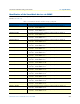
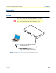
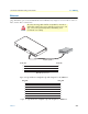
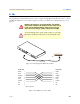

Table Of Contents
- Summary Table of Contents
- Table of Contents
- List of Figures
- List of Tables
- About this guide
- Chapter 1 General information
- Chapter 2 Applications overview
- Chapter 3 SmartNode installation
- Chapter 4 Initial configuration
- Chapter 5 G.SHDSL Basic Configuration
- Chapter 6 Contacting Patton for assistance
- Appendix A Compliance information
- Appendix B Specifications
- Appendix C Cabling
- Appendix D Port pin-outs
- Appendix E SmartNode 4950-NCE factory configuration
- Appendix F End user license agreement

Introduction 54
SmartNode 4950-NCE Getting Started Guide C • Cabling
Introduction
This section provides information on the cables used to connect the SmartNode and the interface cards to the
existing network infrastructure and to third party products.
Console
The SmartNode can be connected to a serial terminal over its serial console port, as depicted in figure 9.
Figure 9. Connecting a serial terminal
Note
See section “Console port” on page 59 for console port pin-outs.
The interconnecting cables shall be acceptable for external use
and shall be rated for the proper application with respect to volt-
age, current, anticipated temperature, flammability, and
mechanical serviceability.
CAUTION
Serial Terminal
Note A Patton Model 16F-561 RJ45 to DB-9 adapter is included with
each SmartNode 4960 Series device
RS-232
C
onsole
E
TH 0/0
ETH
0/1
Reset
0/0
0
/1
0/2
0/3
T1/E1