
- Patton Electronics Network Router User Manual
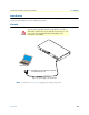
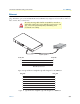
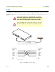

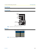
Table Of Contents
- Summary Table of Contents
- Table of Contents
- List of Figures
- List of Tables
- About this guide
- Chapter 1 General information
- Chapter 2 Applications overview
- Chapter 3 SmartNode installation
- Chapter 4 Initial configuration
- Chapter 5 G.SHDSL Basic Configuration
- Chapter 6 Contacting Patton for assistance
- Appendix A Compliance information
- Appendix B Specifications
- Appendix C Cabling
- Appendix D Port pin-outs
- Appendix E SmartNode 4950-NCE factory configuration
- Appendix F End user license agreement

Ethernet 55
SmartNode 4950-NCE Getting Started Guide C • Cabling
Ethernet
Ethernet devices (10Base-T/100Base-T/1000Base-T) are connected to the SmartNode over a cable with RJ-45
plugs. All Ethernet ports on the SN4950-NCE are Auto-MDX use any straight or crossover cable to connect to
hubs, switches, PCs or other devices.
Figure 10. Typical Ethernet straight-through cable diagram for 10/100Base-T
Figure 11. Typical Ethernet straight-through cable diagram for 1000Base-T
The interconnecting cables shall be acceptable for external use
and shall be rated for the proper application with respect to volt-
age, current, anticipated temperature, flammability, and
mechanical serviceability.
CAUTION
Hub
RJ-45, male
1
2
3
6
RJ-45, male
1
2
3
6
Straight-through cable
Note: Other pins are not used.
R
S-2
32
Console
ETH
0/0
E
TH 0
/1
Reset
0/0
0/1
0/2
0/3
T1/E1
RJ-45, male
1
2
3
6
4
5
7
8
RJ-45, male
1
2
3
6
4
5
7
8