For Quick Start Installation SmartNode 4940 Series Multi-Port T1/E1/PRI Enterprise VoIP Media Gateway Getting Started Guide Sales Office: +1 (301) 975-1000 Technical Support: +1 (301) 975-1007 E-mail: support@patton.com WWW: www.patton.com Part Number: 07MSN4940-GS, Rev.
Patton Electronics Company, Inc. 7622 Rickenbacker Drive Gaithersburg, MD 20879 USA Tel: +1 (301) 975-1000 Fax: +1 (301) 869-9293 Support: +1 (301) 975-1007 Web: www.patton.com E-mail: support@patton.com Trademark Statement The terms SmartNode and SmartWare are trademarks of Patton Electronics Company. All other trademarks presented in this document are the property of their respective owners. Copyright © 2011, Patton Electronics Company. All rights reserved.
Summary Table of Contents 1 General information ...................................................................................................................................... 13 2 Applications overview.................................................................................................................................... 20 3 SmartNode installation..................................................................................................................................
Table of Contents Summary Table of Contents ........................................................................................................................... 3 Table of Contents ........................................................................................................................................... 4 List of Figures ................................................................................................................................................. 7 List of Tables ...
SmartNode 4940 Getting Started Guide Table of Contents Factory-default IP settings ...............................................................................................................................28 Connecting the SmartNode to the network ...........................................................................................................28 Loading the configuration (optional) ..............................................................................................................
SmartNode 4940 Getting Started Guide Table of Contents C Cabling ......................................................................................................................................................... 47 Introduction ..........................................................................................................................................................48 Console ..............................................................................................................
List of Figures 1 2 3 4 5 6 7 8 9 10 11 12 13 14 SmartNode 4940 . . . . . . . . . . . . . . . . . . . . . . . . . . . . . . . . . . . . . . . . . . . . . . . . . . . . . . . . . . . . . . . . . . . . . . . 14 SN4940 rear panel . . . . . . . . . . . . . . . . . . . . . . . . . . . . . . . . . . . . . . . . . . . . . . . . . . . . . . . . . . . . . . . . . . . . . . 16 SmartNode 4940 front panel . . . . . . . . . . . . . . . . . . . . . . . . . . . . . . . . . . . . . . . . . . . . . . . . . . . . . . . . .
List of Tables 1 2 3 4 5 6 7 8 9 10 General conventions . . . . . . . . . . . . . . . . . . . . . . . . . . . . . . . . . . . . . . . . . . . . . . . . . . . . . . . . . . . . . . . . . . . . . 12 SmartNode 4940 PRI Ports and Voice Channels . . . . . . . . . . . . . . . . . . . . . . . . . . . . . . . . . . . . . . . . . . . . . . . 15 Rear panel ports . . . . . . . . . . . . . . . . . . . . . . . . . . . . . . . . . . . . . . . . . . . . . . . . . . . . . . . . . . . . . . . . . . . . . . . .
About this guide This guide describes the SmartNode 4940 hardware, installation and basic configuration. For detailed software configuration information refer to the SmartWare Software Configuration Guide and the available Configuration Notes.
SmartNode 4940 Getting Started Guide Precautions Notes, cautions, and warnings, which have the following meanings, are used throughout this guide to help you become aware of potential problems. Warnings are intended to prevent safety hazards that could result in personal injury. Cautions are intended to prevent situations that could result in property damage or impaired functioning. Note A note presents additional information or interesting sidelights.
SmartNode 4940 Getting Started Guide Safety when working with electricity • Do not open the device when the power cord is connected. For systems WARNING • • • • • • without a power switch and without an external power adapter, line voltages are present within the device when the power cord is connected.
SmartNode 4940 Getting Started Guide Always follow ESD prevention procedures when removing and replacing cards. CAUTION Wear an ESD-preventive wrist strap, ensuring that it makes good skin contact. Connect the clip to an unpainted surface of the chassis frame to safely channel unwanted ESD voltages to ground. To properly guard against ESD damage and shocks, the wrist strap and cord must operate effectively. If no wrist strap is available, ground yourself by touching the metal part of the chassis.
Chapter 1 General information Chapter contents SmartNode 4940 overview ....................................................................................................................................14 SN4940 model codes ......................................................................................................................................15 SN4941 model codes .................................................................................................................................
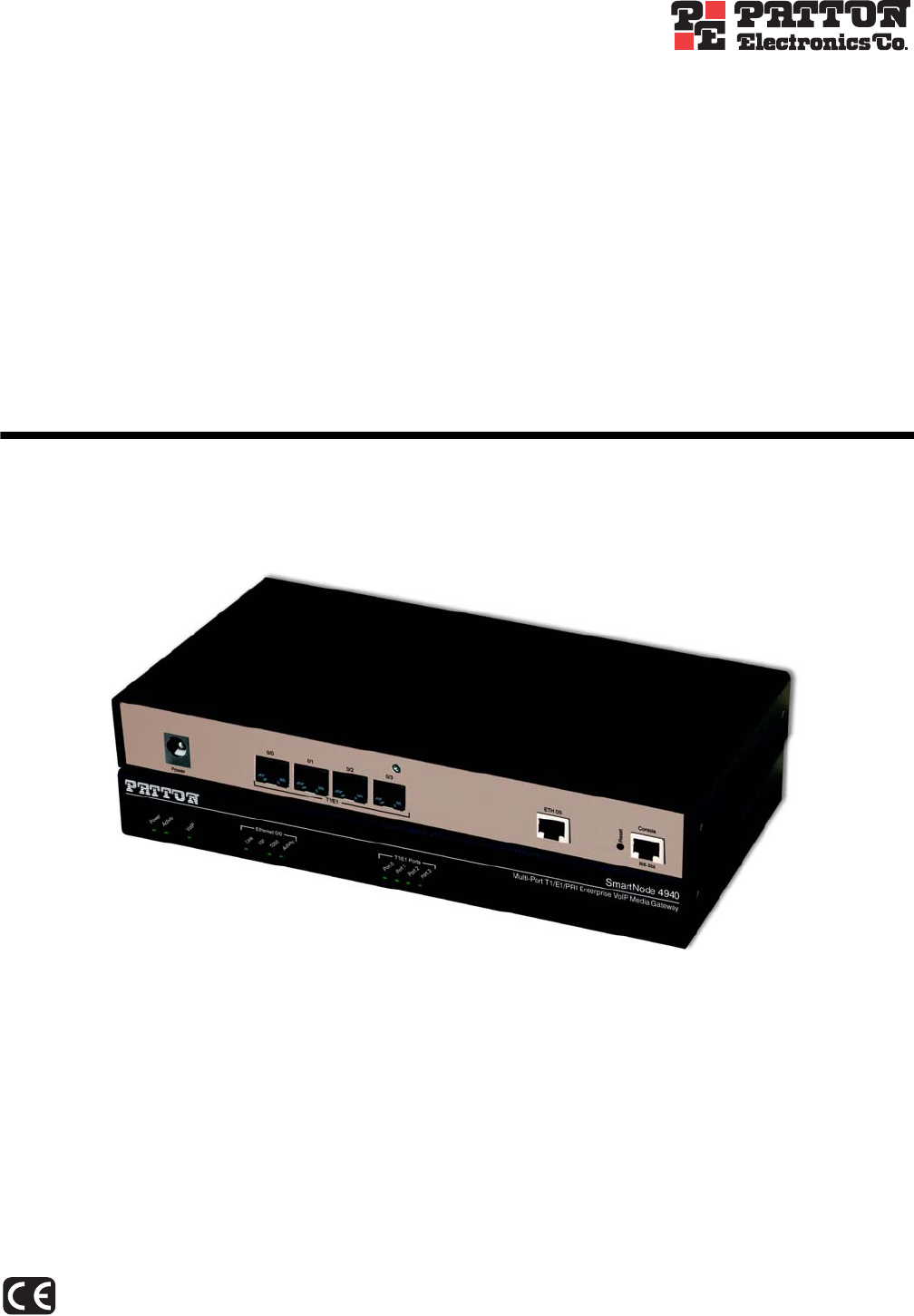
SmartNode 4940 Getting Started Guide 1 • General information SmartNode 4940 overview As enterprises move toward unified communications, the SmartNode™ 4940 Enterprise VoIP Media Gateway (see figure 1) provides a smooth transition by either IP-enabling traditional PBX systems for SIP trunking over existing Internet connection, adding PSTN-breakout for number portability, or enabling PSTN access for IP PBX and unified communications systems.
SmartNode 4940 Getting Started Guide 1 • General information SN4940 model codes The SmartNode 4940 series consists of several models. They differ in the number of PRI ports and voice channels supported. All models come equipped with one 10/100/1000Base-T Ethernet port. The SmartNode 4940 PRI ports and voice channels are listed in table 2. Table 2.
SmartNode 4940 Getting Started Guide 1 • General information SmartNode 4940 rear panel The SmartNode 4940 rear panel ports are described in table 3. 0/3 0/2 0/1 T1 /E 0/0 1 H 0/1 Reset ET Con so RS- le 23 2 Power SN4940/1E30V 0/0 Console Reset ETH 0/0 T1/E1 RS-232 T1/E1 PRI port 0/0 SN4940/4E120V 0/2 0/1 0/0 ETH 0/0 Console Reset 0/3 T1/E1 RS-232 T1/E1 PRI ports 0/3–0/0 Console RS-232 port ETH 0/0 10/100/1000Base-T port RESET button Figure 2.
SmartNode 4940 Getting Started Guide 1 • General information Table 3. Rear panel ports Port Description ETH 0/0 Auto-MDX Gigabit-Ethernet port, RJ-45 (see figure 2), connects the unit to an Ethernet WAN device (for example, a cable modem, DSL modem, or fiber modem). Note: Only full duplex modes are supported. PRI 0/0 RJ-45 connector providing E1 (2.048Mbps) or T1(1.533 Mbps) PRI interface, meeting all requirements of ITU-T recommendations for G.703.
SmartNode 4940 Getting Started Guide 1 • General information SmartNode 4940 front panel Figure 3 shows SmartNode 4940 front panel LEDs, the LED definitions are listed in table 4.
SmartNode 4940 Getting Started Guide 1 • General information Table 4. SN4940 Front and Rear panel LEDs LED Description Note If an error occurs, all LEDs will flash once per second. Power When lit, indicates power is applied. Run When lit, the unit is in normal operation. Flashes once per second during boot (startup). VoIP Link • On indicates the gateway is registered to an H.323 gatekeeper/SIP server, or, in the case of direct routing, has at least one active VoIP connection.
Chapter 2 Applications overview Chapter contents Introduction ..........................................................................................................................................................21 Application—Convert Legacy PBX to VoIP ..........................................................................................................
SmartNode 4940 Getting Started Guide 2 • Applications overview Introduction Patton’s SmartNode Enterprise VoIP Media Gateways deliver the features you need for advanced multiservice voice and data network applications. They combine high quality voice-over-IP with powerful quality of service routing functions to build professional and reliable VoIP and data networks. This chapter describes typical applications for which this SmartNode is uniquely suited.
Chapter 3 SmartNode installation Chapter contents Planning the installation........................................................................................................................................23 Site log ............................................................................................................................................................23 Network information ............................................................................................................
SmartNode 4940 Getting Started Guide 3 • SmartNode installation Planning the installation Before installing the gateway router device, the following tasks should be completed: • Create a network diagram (see section “Network information” on page 23) • Gather IP related information (see section “IP related information” on page 23 for more information) • Install the hardware and software needed to configure the SmartNode.
SmartNode 4940 Getting Started Guide 3 • SmartNode installation • IP addresses of central H.323 gatekeeper (if used) • IP addresses and/or URL of SIP servers or Internet telephony services (if used) • Login and password for SIP or H.
SmartNode 4940 Getting Started Guide 3 • SmartNode installation Connect the cables in the following order: CAUTION The interconnecting cables shall be acceptable for external use and shall be rated for the proper application with respect to voltage, current, anticipated temperature, flammability, and mechanical serviceability. 1. Connect the T1/E1 cables to the PRI T1/E1 ports (see Appendix C on page 47 and Appendix D on page 52). 2.
SmartNode 4940 Getting Started Guide 3 • SmartNode installation Connecting the power supply • Do not connect power to the AC Mains at this time. WARNING CAUTION • The external power adapter shall be a listed Limited Power Source. • The 4940 external power supply automatically adjusts to accept an input voltage from 100 to 240 VAC (50/60 Hz). Verify that the proper voltage is present before plugging the power cord into the receptacle. Failure to do so could result in equipment damage. 1.
Chapter 4 Initial configuration Chapter contents Introduction ..........................................................................................................................................................28 Configuring the desired IP address ........................................................................................................................28 Factory-default IP settings .........................................................................................................
SmartNode 4940 Getting Started Guide 4 • Initial configuration Introduction This chapter leads you through the basic steps to set up a new SmartNode and to download a configuration. Setting up a new SmartNode consists of the following main steps: Note If you haven’t already installed the SmartNode, refer to chapter 3, “SmartNode installation” on page 22.
SmartNode 4940 Getting Started Guide 4 • Initial configuration 0/3 0/2 0/1 T1 /E1 0/0 ET H 0/1 Reset LAN Co ns ole RS -23 2 LAN (ETH 0/0) Figure 6. Connecting the SmartNode to the network You can check the connection with the ping command from the SmartNode to another host on the network. 172.16.1.
SmartNode 4940 Getting Started Guide 4 • Initial configuration After the SmartNode has been rebooted the new startup configuration will be activated. IMPORTANT When you issue the reload command, the SmartNode will ask if you want to copy the running configuration to the startup configuration. Since you just downloaded a configuration file to the startup configuration you must answer this question with NO. Otherwise, the downloaded configuration will be overwritten and lost! 172.16.1.
SmartNode 4940 Getting Started Guide 4 • Initial configuration Start-up with factory configuration Step Command Purpose 1 RedBoot> fis load Copies the SmartWare application image from the persistent memory (flash:) to the volatile memory (RAM) from where it will be executed. 2 RedBoot> go -s factory-config Starts the SmartWare application telling it to use ‘factory-config’ as startup configuration.
SmartNode 4940 Getting Started Guide Step 8 4 • Initial configuration Command RedBoot> go Purpose Starts the application image that was downloaded into the volatile memory (RAM). Note With the Bootloader, only the Ethernet interface 0/0 is available. The Bootloader applies the IP address, subnet mask, and default gateway that were last configured by the Bootloader itself or by another application (e.g. SmartWare).
SmartNode 4940 Getting Started Guide 4 • Initial configuration Load a new application image (SmartWare) via the serial link The Bootloader supports the ‘X-Modem’ and ‘Y-Modem’ protocols to download application images via the serial link of the console. Do the following to initiate the download: Step Command Purpose 1 RedBoot> load -r -v -m { xmodem | ymodem } -b base_address Downloads an application image into the volatile memory (RAM) from where the SmartNode could directly execute it.
Chapter 5 Contacting Patton for assistance Chapter contents Introduction ..........................................................................................................................................................36 Contact information..............................................................................................................................................36 Patton support headquarters in the USA .............................................................................
SmartNode 4940 Getting Started Guide 5 • Contacting Patton for assistance Introduction This chapter contains the following information: • “Contact information”—describes how to contact Patton technical support for assistance. • “Warranty Service and Returned Merchandise Authorizations (RMAs)”—contains information about the warranty and obtaining a return merchandise authorization (RMA). Contact information Patton Electronics offers a wide array of free technical services.
SmartNode 4940 Getting Started Guide 5 • Contacting Patton for assistance Out-of-warranty service Patton services what we sell, no matter how you acquired it, including malfunctioning products that are no longer under warranty. Our products have a flat fee for repairs. Units damaged by lightning or other catastrophes may require replacement.
Appendix A Compliance information Chapter contents Compliance ...........................................................................................................................................................39 EMC ...............................................................................................................................................................39 Safety .......................................................................................................................
SmartNode 4940 Getting Started Guide A • Compliance information Compliance EMC • FCC Part 15, Class A • EN55022, Class A • EN55024 Safety • UL 60950-1/CSA C22.2 N0.
SmartNode 4940 Getting Started Guide A • Compliance information FCC Part 68 (ACTA) Statement This equipment complies with Part 68 of FCC rules and the requirements adopted by ACTA. On the bottom side of this equipment is a label that contains—among other information—a product identifier in the format US: AAAEQ##TXXXX. If requested, this number must be provided to the telephone company.
SmartNode 4940 Getting Started Guide A • Compliance information CE Declaration of Conformity This equipment conforms to the requirements of Council Directive 1999/5/EC on the approximation of the laws of the member states relating to Radio and Telecommunication Terminal Equipment and the mutual recognition of their conformity. The safety advice in the documentation accompanying this product shall be obeyed. The conformity to the above directive is indicated by CE sign on the device.
Appendix B Specifications Chapter contents Voice connectivity .................................................................................................................................................43 Data connectivity ..................................................................................................................................................43 Voice processing (signalling dependent) ...............................................................................................
SmartNode 4940 Getting Started Guide Note B • Specifications Refer to the software feature matrix for the most up-to-date specifications.
SmartNode 4940 Getting Started Guide B • Specifications G.711 Fax-Bypass Voice signalling SIPv2 H.
SmartNode 4940 Getting Started Guide B • Specifications Management Web-based GUI Industry standard CLI with local console (RJ-45, RJ-231, 9600 bps, 8, N, 1) and remote Telnet access, fully documented HTTP web management and firmware loading TFTP configuration & firmware loading SNMP v1 agent (MIB II and private MIB) Built-in diagnostic tools (trace, debug) Secure Auto-provisioning System CPU Motorola MPC8360 series operating at 266/400 MHz Memory: • 128 Mbytes RAM (DDR, 266MHz) • 8 Mbytes Flash Physical
SmartNode 4940 Getting Started Guide B • Specifications Identification of the SmartNode devices via SNMP All SmartNode devices have assigned sysObjectID (.iso.org.dod.internet.mgmt.mib-2.system.sysObjectID) numbers (see table 7). Table 7. SmartNode Models and their Unique sysObjectID SmartNode Model SysObjectID SN4940/1E15V .iso.org.dod.internet.private.enterprises.patton.products.sn49xx.1 1.3.6.1.4.1.1768.100.4.16.1 SN4940/1E24V .iso.org.dod.internet.private.enterprises.patton.products.sn49xx.2 1.3.
SmartNode 4940 Getting Started Guide B • Specifications Table 7. SmartNode Models and their Unique sysObjectID (Continued) SmartNode Model SN4941/4E120V Note SysObjectID .iso.org.dod.internet.private.enterprises.patton.products.sn49xx.20 1.3.6.1.4.1.1768.100.4.16.20 The SysObjectIDs for the SN4940 G.SHDSL models are the same as the corresponding non-G.SHDSL models listed above. According to table 7, an SNMP get request to .iso.org.dod.internet.mgmt.mib-2.system.
Appendix C Cabling Chapter contents Introduction ..........................................................................................................................................................49 Console .................................................................................................................................................................49 Ethernet .............................................................................................................................
SmartNode 4940 Getting Started Guide C • Cabling Introduction This section provides information on the cables used to connect the SmartNode and the interface cards to the existing network infrastructure and to third party products. Console The SmartNode can be connected to a serial terminal over its serial console port, as depicted in figure 7.
SmartNode 4940 Getting Started Guide C • Cabling Ethernet Ethernet devices (10Base-T/100Base-T/1000Base-T) are connected to the SmartNode over a cable with RJ-45 plugs. The Ethernet port on the SN4940 is Auto-MDX and uses any straight or crossover cable to connect to hubs, switches, PCs or other devices.
SmartNode 4940 Getting Started Guide C • Cabling E1 PRI The E1 PRI is usually connected to a PBX or switch—local exchange (LE). Type and pin outs of these devices vary depending on the manufacturer. In most cases, a straight-through RJ-45 to RJ-45 can be used to connect the PRI with a PBX. A cross-over cable is required to connect to an NT device, as illustrated in figure 10 on page 50. Hazardous network voltages are present in the PRI cables.
SmartNode 4940 Getting Started Guide C • Cabling T1 PRI The T1 PRI is usually connected to a PBX or switch—local exchange (LE). Type and pin outs of these devices vary depending on the manufacturer. In most cases, a straight-through RJ-45 to RJ-45 can be used to connect the PRI with a PBX. A cross-over cable is required to connect to an NT device, as illustrated in figure 12 on page 51. Hazardous network voltages are present in the PRI cables.
Appendix D Port pin-outs Chapter contents Introduction ..........................................................................................................................................................53 Console port..........................................................................................................................................................53 Ethernet ..........................................................................................................................
SmartNode 4940 Getting Started Guide D • Port pin-outs Introduction This section provides pin-out information for the ports of the SmartNode. Console port Configuration settings: 9600 bps, 8 bits, no parity, 1 stop bit, no flow control 8–RTS (N/C) 7–CTS (N/C) 6–TD 5–RD 4–SG 3–DTR 2–CD (N/C) 1–DSR 1 2 3 4 5 6 7 8 Pins 1 & 3 are connected together Figure 14. EIA-561 (RJ-45 8-pin) port Note N/C means no internal electrical connection. Ethernet Table 8.
SmartNode 4940 Getting Started Guide D • Port pin-outs Table 9. RJ45 socket 1000Base-T Pin Signal 1 TRD0+ 2 TRD0- 3 TRD1+ 6 TRD1- 4 TRD2+ 5 TRD2- 7 TRD3+ 8 TRD3- PRI port Table 10. RJ-45 socket Note PRI port Pin USR 1 RX Ring 2 RX Tip 3 RX Shield 4 TX Ring 5 TX Tip 6 TX Shield Pins not listed are not used.
Appendix E SmartNode 4940 factory configuration Chapter contents Introduction ..........................................................................................................................................................
SmartNode 4940 Getting Started Guide E • SmartNode 4940 factory configuration Introduction The factory configuration settings for SmartNode 4940 are as follows: #----------------------------------------------------------------# # # # 4940 Series # # Factory configuration file # # # #----------------------------------------------------------------# sntp-client sntp-client server primary 129.132.2.
Appendix F End user license agreement Chapter contents End User License Agreement .................................................................................................................................58 1. Definitions ..................................................................................................................................................58 2. Title .............................................................................................................................
SmartNode 4940 Getting Started Guide F • End user license agreement End User License Agreement By opening this package, operating the Designated Equipment or downloading the Program(s) electronically, the End User agrees to the following conditions: 1. Definitions A) Effective Date shall mean the earliest date of purchase or download of a product containing the Patton Electronics Company Program(s) or the Program(s) themselves.
SmartNode 4940 Getting Started Guide F • End user license agreement If the Program(s) are acquired by or on behalf of a unit or agency of the United States Government, the Government agrees that such Program(s) are commercial computer software or computer software documentation and that, absent a written agreement to the contrary, the Government’s rights with respect to such Program(s) are limited by the terms of this Agreement, pursuant to Federal Acquisition Regulations 12.212(a) and/or DEARS 227.