
- Patton Electronics Network Router User Manual
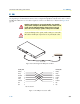
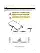
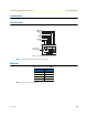
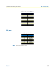
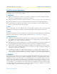
Table Of Contents
- Summary Table of Contents
- Table of Contents
- List of Figures
- List of Tables
- About this guide
- Chapter 1 General information
- Chapter 2 Applications overview
- Chapter 3 SmartNode installation
- Chapter 4 Initial configuration
- Chapter 5 Contacting Patton for assistance
- Appendix A Compliance information
- Appendix B Specifications
- Appendix C Cabling
- Appendix D Port pin-outs
- Appendix E SmartNode 4940 factory configuration
- Appendix F End user license agreement
Introduction 53
SmartNode 4940 Getting Started Guide D • Port pin-outs
Introduction
This section provides pin-out information for the ports of the SmartNode.
Console port
Configuration settings: 9600 bps, 8 bits, no parity, 1 stop bit, no flow control
Figure 14. EIA-561 (RJ-45 8-pin) port
Note
N/C means no internal electrical connection.
Ethernet
Note
Pins not listed are not used.
Table 8. RJ45 socket 10/100Base-T
Pin Signal
1 TX+
2 TX-
3 RX+
6 RX-
12345678
8–RTS (N/C)
7–CTS (N/C)
6–TD
5–RD
4–SG
3–DTR
2–CD (N/C)
1–DSR
Pins 1 & 3 are
connected together