For Quick Start Installation SmartNode 5400 Series Enterprise Session Border Router Getting Started Guide Important This is a Class A device and is not intended for use in a residential environment. Sales Office: +1 (301) 975-1000 Technical Support: +1 (301) 975-1007 E-mail: support@patton.com WWW: www.patton.com Part Number: 07MSN5400-GS, Rev.
Patton Electronics Company, Inc. 7622 Rickenbacker Drive Gaithersburg, MD 20879 USA Tel: +1 (301) 975-1000 Fax: +1 (301) 869-9293 Support: +1 (301) 975-1007 Web: www.patton.com E-mail: support@patton.com Trademark Statement The terms SmartNode and SmartWare are trademarks of Patton Electronics Company. All other trademarks presented in this document are the property of their respective owners. Copyright © 2010, Patton Electronics Company. All rights reserved.
Summary Table of Contents 1 General information ...................................................................................................................................... 14 2 Applications overview.................................................................................................................................... 20 3 SmartNode installation..................................................................................................................................
Table of Contents Summary Table of Contents ........................................................................................................................... 3 Table of Contents ........................................................................................................................................... 4 List of Figures ................................................................................................................................................. 7 List of Tables ...
SmartNode 5400 Getting Started Guide Table of Contents 2. Configuring the desired IP address ....................................................................................................................29 Factory-default IP settings ...............................................................................................................................29 Login ......................................................................................................................................
SmartNode 5400 Getting Started Guide Table of Contents Data connectivity ..................................................................................................................................................47 Voice processing (signalling dependent) ................................................................................................................47 Fax and modem support................................................................................................................
List of Figures 1 2 3 4 5 6 7 8 9 10 11 12 SN5400 rear panel . . . . . . . . . . . . . . . . . . . . . . . . . . . . . . . . . . . . . . . . . . . . . . . . . . . . . . . . . . . . . . . . . . . . . . 16 SmartNode 5400 front panel . . . . . . . . . . . . . . . . . . . . . . . . . . . . . . . . . . . . . . . . . . . . . . . . . . . . . . . . . . . . . . 18 SN5400 typical application . . . . . . . . . . . . . . . . . . . . . . . . . . . . . . . . . . . . . . . . . . . . . . . . . . . . . . . . . . . . . . .
List of Tables 1 2 3 4 5 6 7 8 9 10 11 12 13 14 15 General conventions . . . . . . . . . . . . . . . . . . . . . . . . . . . . . . . . . . . . . . . . . . . . . . . . . . . . . . . . . . . . . . . . . . . . . 13 SmartNode 5400 Models . . . . . . . . . . . . . . . . . . . . . . . . . . . . . . . . . . . . . . . . . . . . . . . . . . . . . . . . . . . . . . . . . 15 Rear panel ports . . . . . . . . . . . . . . . . . . . . . . . . . . . . . . . . . . . . . . . . . . . . . . . . . . . . . . . . . . . . . . . .
About this guide This guide describes the SmartNode 5400 hardware, installation and basic configuration. For detailed software configuration information refer to the SmartWare Software Configuration Guide and the available Configuration Notes.
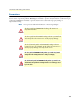
SmartNode 5400 Getting Started Guide Precautions Notes, cautions, and warnings, which have the following meanings, are used throughout this guide to help you become aware of potential problems. Warnings are intended to prevent safety hazards that could result in personal injury. Cautions are intended to prevent situations that could result in property damage or impaired functioning. Note A note presents additional information or interesting sidelights.
SmartNode 5400 Getting Started Guide Safety when working with electricity • Do not open the device when the power cord is connected. For systems • • • • • • without a power switch and without an external power adapter, line voltages are present within the device when the power cord is connected.
SmartNode 5400 Getting Started Guide Electrostatic Discharge (ESD) can damage equipment and impair electrical circuitry. It occurs when electronic printed circuit cards are improperly handled and can result in complete or intermittent failures. Do the following to prevent ESD: • Always follow ESD prevention procedures when removing and replacing cards. • Wear an ESD-preventive wrist strap, ensuring that it makes good skin contact.
SmartNode 5400 Getting Started Guide Typographical conventions used in this document This section describes the typographical conventions and terms used in this guide. General conventions The procedures described in this manual use the following text conventions: Table 1. General conventions Convention Garamond blue type Meaning Indicates a cross-reference hyperlink that points to a figure, graphic, table, or section heading. Clicking on the hyperlink jumps you to the reference.
Chapter 1 General information Chapter contents SmartNode 5400 overview ....................................................................................................................................15 SN5400 model codes ......................................................................................................................................15 SmartNode 5400 rear panel...........................................................................................................................
SmartNode 5400 Getting Started Guide 1 • General information SmartNode 5400 overview The SmartNode 5400 Enterprise Session Border Router enables Universal SIP Trunking and provides a single Integrated Access Device with features like IP Routing, Redundancy, Security and a SIP registrar for survivability. In addition, the SN5400 enables Transcoding between two networks to most optimally support the bandwidth requirements.
SmartNode 5400 Getting Started Guide 1 • General information SmartNode 5400 rear panel The SmartNode 5400 rear panel ports are described in table 3. – + 12 V, 1.25 A AC T LI NK ET H 0/1 0/0 Reset ET H Con so le RS23 2 Power SN5400/xxP/EUI ETH 0/0 Console Reset ETH 0/1 + - 12V, 1.25A RS-232 SN5400/xxP2GS/EUI ACT LINK ETH 0/0 Console Reset ETH 0/1 + - 12V, 1.
SmartNode 5400 Getting Started Guide 1 • General information Table 3. Rear panel ports Port Description WAN ETH 0/0 Auto-MDX Gigabit-Ethernet port, RJ-45 (see figure 1), connects the unit to an Ethernet WAN device (for example, a cable modem, DSL modem, or fiber modem). Note: Only full duplex modes are supported. LAN ETH 0/1 Auto-MDX Gigabit-Ethernet port, RJ-45 (see figure 1), connect the unit to an Ethernet LAN (for example, a PC, printer, or wireless bridge).
SmartNode 5400 Getting Started Guide 1 • General information SmartNode 5400 front panel Figure 2 shows SmartNode 5400 front panel LEDs, the LED definitions are listed in table 4. En terp S e S ma es rtN sio n B ode ord er ris 54 Ro 00 ute r SN5400 SmartNode 5400 Enterprise Session Border Router Power Activity Ethernet 0/1 Activity VoIP Ethernet 0/0 Link Ethernet 0/0 1000 Ethernet 0/0 100 Ethernet 0/1 Link Ethernet 0/0 Activity Ethernet 0/1 1000 Ethernet 0/1 100 Figure 2.
SmartNode 5400 Getting Started Guide 1 • General information Table 4. SN5400 Front and Rear panel LEDs LED Description Note If an error occurs, all LEDs will flash once per second. Power When lit, indicates power is applied. Run When lit, the unit is in normal operation. Flashes once per second during boot (startup). VoIP Link • On indicates the gateway is registered to an H.323 gatekeeper/SIP server, or, in the case of direct routing, has at least one active VoIP connection.
Chapter 2 Applications overview Chapter contents Introduction ..........................................................................................................................................................21 Typical application ................................................................................................................................................
SmartNode 5400 Getting Started Guide 2 • Applications overview Introduction Patton’s SmartNode VoIP Enterprise Session Border Routers deliver the features you need for advanced multiservice voice and data network applications. They combine high quality voice-over-IP with powerful quality of service routing functions to build professional and reliable VoIP and data networks. This chapter describes typical applications for which this SmartNode is uniquely suited.
Chapter 3 SmartNode installation Chapter contents Planning the installation........................................................................................................................................23 Site log ............................................................................................................................................................23 Network information ............................................................................................................
SmartNode 5400 Getting Started Guide 3 • SmartNode installation Planning the installation Before installing the gateway router device, the following tasks should be completed: • Create a network diagram (see section “Network information” on page 23) • Gather IP related information (see section “IP related information” on page 23 for more information) • Install the hardware and software needed to configure the SmartNode.
SmartNode 5400 Getting Started Guide 3 • SmartNode installation • IP addresses of central H.323 gatekeeper (if used) • IP addresses and/or URL of SIP servers or Internet telephony services (if used) • Login and password for PPPoE Access • Login and password for SIP or H.
SmartNode 5400 Getting Started Guide 3 • SmartNode installation Connect the cables in the following order: CAUTION The interconnecting cables shall be acceptable for external use and shall be rated for the proper application with respect to voltage, current, anticipated temperature, flammability, and mechanical serviceability. 1. Connect the 10/100/1000Base-T Ethernet LAN and WAN (see section “Connecting the 10/100/1000Base-T Ethernet LAN and WAN cables” on page 25) 2.
SmartNode 5400 Getting Started Guide 3 • SmartNode installation Connecting the power supply The 5400 has the option of an internal or external Internal AC Power Supply, or an internal or external Verify that the green Power LED is lit (see figure 5).. Internal AC Power Supply. • Do not connect power to the AC Mains at this time. • There are no user-serviceable parts in the power supply sec WARNING tion of the Model 5400.
Chapter 4 Initial configuration Chapter contents Introduction ..........................................................................................................................................................28 1. Connecting the SmartNode to your laptop PC..................................................................................................28 2. Configuring the desired IP address ...........................................................................................................
SmartNode 5400 Getting Started Guide 4 • Initial configuration Introduction This chapter leads you through the basic steps to set up a new SmartNode and to download a configuration. Setting up a new SmartNode consists of the following main steps: Note If you haven’t already installed the SmartNode, refer to chapter 3, “SmartNode installation” on page 22.
SmartNode 5400 Getting Started Guide 4 • Initial configuration 2. Configuring the desired IP address Factory-default IP settings The factory default configuration for the Ethernet interface IP addresses and network masks are listed in table 6. Both Ethernet interfaces are activated upon power-up. LAN interface ETH 0/1 (LAN) provides a default DHCP server, the WAN interface uses DHCP client to automatically assign the IP address and network mask. Table 6.
SmartNode 5400 Getting Started Guide 4 • Initial configuration Now you can set your IP address and network mask for the interface ETH 0/0 (WAN). Within this example a network 172.16.1.0/24 address is assumed. The IP address in this example is set to 172.16.1.99 (you should set this the IP address given to you by your network provider). 192.168.1.1(ctx-ip)[router]#interface WAN 192.168.1.1(if-ip)[WAN]#ipaddress 172.16.1.99 255.255.255.0 2002-10-29T00:09:40 : LOGINFO : Link down on interface WAN.
SmartNode 5400 Getting Started Guide 4 • Initial configuration You can check the connection with the ping command from the SmartNode to another host on the network. 172.16.1.99(if-ip)[WAN]#ping Note If the WAN address is not set to DHCP, to ping a device outside your local LAN you must first configure the default gateway.
SmartNode 5400 Getting Started Guide 4 • Initial configuration 172.16.1.99(if-ip)[WAN]#reload Running configuration has been changed. Do you want to copy the 'running-config' to the 'startup-config'? Press 'yes' to store, 'no' to drop changes : no Press 'yes' to restart, 'no' to cancel : yes The system is going down Bootloader The bootloader ensures that basic operations, network access, and downloads are possible in case of interrupted or corrupted application image downloads.
SmartNode 5400 Getting Started Guide Step 4 • Initial configuration Command Purpose 2 RedBoot> ip_address -g gateway optional Sets the IP address of the default gateway. 3 RedBoot> ping -h tftp-server_ip_address optional Tests the connectivity to the TFTP server. 4 RedBoot> load -r -v -h host -b base_address file_name Downloads an application image into the volatile memory (RAM) from where the SmartNode could directly execute it.
SmartNode 5400 Getting Started Guide 4 • Initial configuration Using default protocol (TFTP) Raw file loaded 0x01800100-0x0199ca6b, 1689964 bytes, assumed entry at 0x01800100 RedBoot> fis delete -n 1 Delete image 1 - continue (y/n)? y ... Erase from 0x60030000-0x601cc974: .......................... RedBoot> fis create Use address 0x01800100, size 1684402 ? - continue (y/n)? y ... Erase from 0x60030000-0x601cb3ba: .......................... ... Program from 0x00011eec-0x00011ef4 at 0x60030000: . ...
SmartNode 5400 Getting Started Guide Step 8 Command RedBoot> go Note 4 • Initial configuration Purpose Starts the application image that was downloaded to the volatile memory (RAM). This type of download takes about 25 minutes since it uses a serial link at only 9600 bps. Additional information For detailed information about configuring and operating guidance, set up procedures, and troubleshooting, refer to the SmartNode Series SmartWare Software Configuration Guide on the CD-ROM.
Chapter 5 G.SHDSL Basic Configuration Chapter contents Introduction ..........................................................................................................................................................37 Line Setup .............................................................................................................................................................37 Configuring PPPoE ................................................................................................
SmartNode 5400 Getting Started Guide 5 • G.SHDSL Basic Configuration Introduction The SN5400 model has an option for a built-in G.SHDSL modem. The modem appears in the configuration as "port dsl 0 0" mode. port dsl 0\ 0\ vpi 8 pvc vci 35 pppoe Profile napt WAN session MyISP use p bind subscriber MySubscriber Subscriber PPP MySubscriber face inter bind router WAN rofile n WAN apt WAN interface context ip Figure 8. Configuring the G.
SmartNode 5400 Getting Started Guide 5 • G.SHDSL Basic Configuration Next, you will need to create a WAN profile, create a WAN interface, and create a subscriber. Then, you can configure the DSL port (port dsl 0 0) for PPPoE.
SmartNode 5400 Getting Started Guide 5 • G.SHDSL Basic Configuration Setting up permanent virtual circuits (PVC) The modems currently available are using ATM to multiplex traffic over the DSL framing connection. ATM allows you to have separate logical connections running in parallel. Those connections are called permanent virtual circuits (PVC). All permanent virtual circuits use AAL5 framing. Table 7.
SmartNode 5400 Getting Started Guide 5 • G.SHDSL Basic Configuration Diagnostics Table 10. Diagnostics commans Command Purpose Step 1 node> show dsl type Displays the type of modem installed. Step 2 node> show dsl line-state Displays information about the state of the DSL link. Step 3 node> show dsl version Display firmware version information for the modem. Step 4 node# debug dsl-setup Lists the configuration interactions between the gateway and the modem module.
Chapter 6 Contacting Patton for assistance Chapter contents Introduction ..........................................................................................................................................................42 Contact information..............................................................................................................................................42 Patton support headquarters in the USA .............................................................................
SmartNode 5400 Getting Started Guide 6 • Contacting Patton for assistance Introduction This chapter contains the following information: • “Contact information”—describes how to contact Patton technical support for assistance. • “Warranty Service and Returned Merchandise Authorizations (RMAs)”—contains information about the warranty and obtaining a return merchandise authorization (RMA). Contact information Patton Electronics offers a wide array of free technical services.
SmartNode 5400 Getting Started Guide 6 • Contacting Patton for assistance Out-of-warranty service Patton services what we sell, no matter how you acquired it, including malfunctioning products that are no longer under warranty. Our products have a flat fee for repairs. Units damaged by lightning or other catastrophes may require replacement.
Appendix A Compliance information Chapter contents Compliance ...........................................................................................................................................................45 EMC ...............................................................................................................................................................45 Low-Voltage Directive (Safety) ...............................................................................................
SmartNode 5400 Getting Started Guide A • Compliance information Compliance EMC • EN55022, Class A • EN55024 Low-Voltage Directive (Safety) • IEC/EN60950-1, 2nd edition PSTN Regulatory • This device is not intended nor approved for connection to the PSTN CE Declaration of Conformity Patton Electronics, Inc declares that this device is in compliance with the essential requirements and other relevant provisions of Directive 1999/5/EC.
Appendix B Specifications Chapter contents Data connectivity ..................................................................................................................................................47 Voice processing (signalling dependent) ................................................................................................................47 Fax and modem support..............................................................................................................................
SmartNode 5400 Getting Started Guide B • Specifications Data connectivity Two 10/100/1000Base-Tx Gigabit Ethernet ports All ports full duplex, autosensing, auto-MDX Voice processing (signalling dependent) Four or eight full-duplex channels with Voice CODECS: • G.711 A-Law/ -Law (64 kbps) • G.726 (ADPCM 16, 24, 32, 40 kbps) • G.723.1 (5.3 or 6.3 kbps) • G.729ab (8 kbps) • Transparent ISDN data G.168 echo cancellation (128 ms) Up to 120 simultaneous voice or T.
SmartNode 5400 Getting Started Guide B • Specifications Configurable progress tones IP services IPv4 router; RIPv1, v2 (RFC 1058 and 2453) Programmable static routes ICMP redirect (RFC 792); Packet fragmentation DiffServe/ToS set or queue per header bits Packet Policing discards excess traffic 802.
SmartNode 5400 Getting Started Guide B • Specifications G.SHDSL Daughter Card (if applicable) Note For information on configuring the G.SHDSL daughter card, see Chapter 5, “G.SHDSL Basic Configuration” on page 36. Table 11. G.SHDSL Daughter Card Specifications Factor Specs DSL • • • • • • ITU-T G.991.2 (and Amendment 2) ITU-T G.991.2, Annex A, B, F, G Upgradable to ITU-T G.shdsl.bis—Annex F and G G.991.2 2/4 (1/2 pair) operation G.994.1 (G.hs) (per G.991.2) ITU-T G.991.2 Section E.
SmartNode 5400 Getting Started Guide B • Specifications Identification of the SmartNode devices via SNMP All SmartNode devices have assigned sysObjectID (.iso.org.dod.internet.mgmt.mib-2.system.sysObjectID) numbers (see table 12). Table 12. SmartNode Models and their Unique sysObjectID SmartNode Model SysObjectID SN5400/32P/EUI .iso.org.dod.internet.private.enterprises.patton.products.sn5400.1 1.3.6.1.4.1.1768.100.4.13.3 SN5400/64P/EUI .iso.org.dod.internet.private.enterprises.patton.products.sn5400.
Appendix C Cabling Chapter contents Introduction ..........................................................................................................................................................52 Console .................................................................................................................................................................52 Ethernet .............................................................................................................................
SmartNode 5400 Getting Started Guide C • Cabling Introduction This section provides information on the cables used to connect the SmartNode and the interface cards to the existing network infrastructure and to third party products. Console The SmartNode can be connected to a serial terminal over its serial console port, as depicted in figure 9.
SmartNode 5400 Getting Started Guide C • Cabling Ethernet Ethernet devices (10Base-T/100Base-T/1000Base-T) are connected to the SmartNode over a cable with RJ-45 plugs. All Ethernet ports on the SN5400 are Auto-MDX use any straight or crossover cable to connect to hubs, switches, PCs or other devices.
Appendix D Port pin-outs Chapter contents Introduction ..........................................................................................................................................................55 Console port..........................................................................................................................................................55 Ethernet ..........................................................................................................................
SmartNode 5400 Getting Started Guide D • Port pin-outs Introduction This section provides pin-out information for the ports of the SmartNode. Console port Configuration settings: 9600 bps, 8 bits, no parity, 1 stop bit, no flow control 8–RTS (N/C) 7–CTS (N/C) 6–TD 5–RD 4–SG 3–DTR 2–CD (N/C) 1–DSR 1 2 3 4 5 6 7 8 Pins 1 & 3 are connected together Figure 12. EIA-561 (RJ-45 8-pin) port Note N/C means no internal electrical connection. Ethernet Table 13.
SmartNode 5400 Getting Started Guide D • Port pin-outs Table 14. RJ45 socket 1000Base-T Pin Signal 1 TRD0+ 2 TRD0- 3 TRD1+ 6 TRD1- 4 TRD2+ 5 TRD2- 7 TRD3+ 8 TRD3- G.SHDSL port Table 15. RJ-45 connector G.
Appendix E SmartNode 5400 factory configuration Chapter contents Introduction ..........................................................................................................................................................
SmartNode 5400 Getting Started Guide E • SmartNode 5400 factory configuration Introduction The factory configuration settings for SmartNode 5400 are as follows: #----------------------------------------------------------------# # # # 5400 Series # # Factory configuration file # # # #----------------------------------------------------------------# dns-relay sntp-client sntp-client server primary 129.132.2.
Appendix F End user license agreement Chapter contents End User License Agreement .................................................................................................................................60 1. Definitions ..................................................................................................................................................60 2. Title .............................................................................................................................
SmartNode 5400 Getting Started Guide F • End user license agreement End User License Agreement By opening this package, operating the Designated Equipment or downloading the Program(s) electronically, the End User agrees to the following conditions: 1. Definitions A) Effective Date shall mean the earliest date of purchase or download of a product containing the Patton Electronics Company Program(s) or the Program(s) themselves.
SmartNode 5400 Getting Started Guide F • End user license agreement If the Program(s) are acquired by or on behalf of a unit or agency of the United States Government, the Government agrees that such Program(s) are commercial computer software or computer software documentation and that, absent a written agreement to the contrary, the Government’s rights with respect to such Program(s) are limited by the terms of this Agreement, pursuant to Federal Acquisition Regulations 12.212(a) and/or DEARS 227.