Power Assist Wheelbarrow Owner’s Manual PAW Model: 44009 PLEASE DON’T RETURN THIS PRODUCT TO THE STORE! - HAVING PROBLEMS? - INSTALLATION QUESTIONS? - NEED PARTS? - TROUBLESHOOTING? CONTACT CUSTOMER SUPPORT FIRST! 1-800-495-9278 WWW.MY-PAW.COM Revised: 01-13 Monday-Friday 8am-5pm Central Time Decko Products - 2301 Traffic St.
Table of Contents Table of contents Congratulations on your purchase Safety guidelines and safety information Battery and tire care Parts inventory Assembling the main frame Assembling drive system Attaching the left handle Attaching electronics box and right handle Attaching the motor protective cover Attaching the battery box Attaching and adjusting wiring Attaching the tray brace Attaching a tray Operating your PAW Attaching the battery charger Charging the ba
Congratulations and Thank You For purchasing your new PAW. We have designed and built your new PAW with the goal of making your life easier. The PAW works great for many applications.
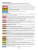
Safety Guidelines Carefully read, understand and follow all safety instructions in this manual. This is the safety alert symbol. When you see this symbol, look for one of the following signal words. DANGER indicates a hazardous situation which, if not avoided, will result in death or serious injury. WARNING indicates a hazardous situation which, if not avoided, could result in death or serious injury.
PAW BATTERIES It is recommended to fully charge your batteries installed in your PAW before each use. Always charge the batteries in the upright position. For best results, charge the batteries while installed in your PAW. When in storage keep the battery box and/or PAW in an upright position with the PAW drive wheels and both support legs flat on level ground.
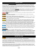
Parts Inventory C B D A E F H G J I K N A. Drive system and electronics I. B. Tray brace J. M8 x 12mm hex bolt (QTY: 2) C. Battery box K. M10 x 25mm hex bolt (QTY: 4) D. Motor protective cover L. M8 x 20mm carriage bolt (QTY: 6) E. Left handle N. M8 hex nut (QTY: 20) F. Left support leg O. Zip tie (QTY: 5) G. Right support leg P. Owner’s Manual H. Dump support brace Q. Battery charger I.
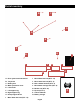
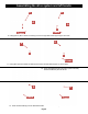
Assembling the main frame 1. Lay out the left support leg (F), right support leg (G), and dump support brace (H) as shown. F H G G G H H 2. Insert the right support leg (G) into the dump support brace (H) as shown above. N N I I 3. Using (QTY 2) M8 x 35mm hex bolts (I) and (QTY 2) M8 hex nuts (N) secure the right support leg (G) to the dump support brace (H). F F H H 4. Insert the left support leg (F) into the dump support brace (H) as shown above.
Assembling the main frame and drive system I I N N 5. Using (QTY 2) M8 x 35mm hex bolts (I) and (QTY 2) M8 hex nuts (N) secure the left support leg (F) to the dump support brace (H). Align the legs and tighten fasteners securely. A Frame E 6. Lay out the drive system and electronics (A), left handle (E), and completed frame as shown above Frame A Frame E B A A 7.
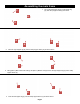
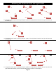
Assembling the drive system and left handle K K A A R R Frame Frame 10. Using (QTY 2) M10 x 25mm hex bolts (K) secure the right side frame support (R) to the frame. K K L L Frame 11. Using (QTY 2) M10 x 25mm hex bolts (K) secure the left side frame support (L) to the frame. 12. Once assembled the frame and drive system assembly should look like the photo at the left. E E Frame Frame 13. Insert the left handle (E) into the assembled frame as shown in the above photo.
Attaching the electronics box and right handle E E A N E N A A I I I Frame Frame Frame 14. Using (QTY 1) M8 x 35mm hex bolts (I) and (QTY 1) M8 hex nuts (N) attach the electronic box (A) to the frame and left handle (E). E I N Frame 15. Using (QTY 1) M8 x 35mm hex bolts (I) and (QTY 1) M8 hex nuts (N) attach the electronic box (A) to the frame and left handle (E). A A Frame A Frame Frame 16.
Attaching the motor protective cover 18.IMPORTANT! Tighten all frame bolts using wrenches. Take special care to make sure all frame parts are aligned. D D 19. Insert the motor protective cover (D) under the assembled frame and drive system as shown in the above images. Take care not to damage the drive system when attaching the motor protective cover (D). N J N D D J 20. Using (QTY 2) M8 x 12mm hex bolts (J) and (QTY 2) M8 hex nuts (N) attach the front of the motor protective cover (D) to the frame.
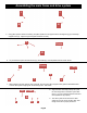
Attaching the battery box C Battery Mounts Battery Mounts Handle Cable C Frame Frame 22. Positioning the handle side of the battery box to the rear - Insert the right side (spring side) of the battery box (C) into the right battery mount holes located in the frame. The drive system electronics cable should go over the top of the battery box (C) as shown. Battery Mounts Battery Mount C C Frame Frame 23.
Attaching and adjusting wiring O Cable Cable Power Plug O Frame Frame Power Plug Slack 26. Using a zip tie (O) secure the power plug wire and drive system electronics cable to the frame. Be sure to leave enough slack so the power plug can be pulled easily from the battery box for recharging. O O Slack Slack Frame Frame 27. Using a zip tie (O) secure the power plug wire and drive system electronics cable to the frame as shown in the above photos.
Attaching the tray brace Brace Extensions B Frame B Plastic tray B Frame Metal tray Frame 31. Slide the tray brace (B) onto the frame brace extensions. Note: there are two separate heights the tray brace (B) can be set. The taller setting is used for plastic trays. The shorter setting is used for metal trays. Plastic Tray N Plastic Tray B B N I I Frame Frame 32. For a plastic tray, mount the tray brace (B) in the taller setting.
Attaching a tray (sold separately) *Purchase a 6 Cu. Ft. plastic or metal tray, sold separately 36. Lower the tray* onto the PAW frame. Line up all holes in the tray with the holes in the PAW frame brackets. 6 Cu. Ft. Tray Frame Brackets Frame Suggestion: It will be easier to insert all 6 mounting bolts if you do not tighten them until they are all in place. L-Top 37. Install (QTY 2) M8 x 20mm carriage bolts (L-Top) into the front/top two holes of the tray.
Operating your PAW 41. Watch for Hazards: Using the PAW on or near steep inclines can cause your PAW to be uncontrollable and cause injury to yourself & others and or damage to property. On steep inclines/ declines, the PAW could reach an unsafe speed. Operating the PAW on steep inclines/declines can cause the PAW to tilt, tip, or possibly roll over. Another danger is loss of drive wheel traction.
Only charge your PAW batteries in an open, dry, well-ventilated area. ONLY use the charger supplied with your PAW. Use of other charging systems could damage the unit and may cause harm to you. If your indicator light does not change to green within 24 hours, call us at 1-800-495-9278 or visit us online at my-paw.com. The charger has a built in safety switch that prevents overcharging of the batteries.
Operating your Paw 54. Operation: With the power button in the ON position, a direction selected (forward or reverse), both hands on the handles and solid footing SLOWLY press the thumb throttle located on the right handle. This is the variable speed/ power control. The further the thumb throttle is pressed down, the more speed/power your PAW will develop. It is recommended to start at slower speeds of operation until you feel comfortable with your PAW.
Troubleshooting Problem Possible Cause Charge the battery. A new battery should have been charged for at least 12 hours before using the PAW for the first time. After first-time use, recharge the battery until the green charge light illuminates. Undercharged battery . PAW does not run. Solution PAW was running but suddenly stopped. Short run time (less than 1-3 hours per charge). Check all connectors.
LIMITED WARRANTY AND LIMITATION OF LIABILITY Decko Products warrants this product, to the original purchaser, for the initial residence in which it is located (upon verif ication that it is assembled correctly) to be free from defects in materials and or workmanship for a period of 1 YEAR from the date of purchase, with the exception that certain components which wear out upon normal use are excluded from this warranty.