Users Manual 610 / 611 / 612 Printers PAXAR Systems Group Manual Edition 2.
This page left blank intentionally.
Contents Getting Started 1 Audience.............................................................................................................................. 2 Unpacking the Printer........................................................................................................... 2 Connecting the Power Cable................................................................................................. 2 Establishing Communications..............................................................
Lubricating the Knife ......................................................................................................... 43 Troubleshooting 44 Printing a Test Label .......................................................................................................... 45 Troubleshooting................................................................................................................. 46 Error Messages ................................................................................
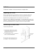
Getting Started The Paxar 610 / 611 / 612 Care Label printers let you print text, graphics, and bar codes on thermal transfer (ribbon) fabric labels. This chapter includes information about ♦ Unpacking the printer. ♦ Connecting the power cord. ♦ Connecting the communications cable. ♦ Using the printer's control panel.
Audience The Operator's Handbook is for the person who prints and applies labels. Unpacking the Printer After you unpack the printer, you should have: a 610 / 611 / 612 printer, power cord, communication cable and a ribbon take-up core (may already be on take-up reel). Keep the box and packaging material in case the printer ever needs repair. Power cords are not supplied with 230-volt printers. You need to purchase a power cord separately.
Establishing Communications Before the printer can accept print jobs from the host, you must: ♦ Connect the communication cable to the printer and to the host. ♦ Set the communication values on the printer to match those at the host. (Only required if you are using the serial port.) Connecting the Communication Cable Make sure the printer is off before connecting the cable to the communication port. Your printer is supplied with a parallel printer cable.
Default Printer Settings These defaults can be changed using Paxar's PCMate software. Print Speed - 4.0 ips (inches per second), Ribbon - High Energy, Supply Type - Black Mark, Contrast - 255, Backfeed - Enabled, Dispense Position - 120 dots, Backfeed Distance - 110 dots. Using the Control Panel The control panel helps you check printer status, displays error codes, and allows you to perform some basic printer functions. Printer Status Lights Power: The printer shows a steady green light when it is on.
Button Functions Feed: Prints a label in the On-Demand mode. Feeds a blank label if there is no print job. Prints a label with error information that is useful to your System Administrator if an error is displayed. Pause: Pauses the current print job or resumes a paused print job. When the Paused light is on, the job is paused. Feed and Pause: Prints a test label when you press the buttons at the same time. Feed and Clear: Allows you to adjust print positions from paused mode.
Setting Dip Switches To change the DIP switch settings, move the switches to the desired position and then turn on the printer. If you select Software Controlled, the parameters in Packet F will override the communication settings. Software Controlled uses the last sent Packet F settings or the defaults. Turning on the printer activates the DIP switch settings. Make sure the DIP switch settings match the printer's setup for ribbon or supply type.
DIP Switches Upper DIP Switches Baud Rate 38400 19200 9600 4800 2400 1200 Software Control Data Bits 7 Data Bits 8 Data Bits Stop Bits 2 Stop Bits 1 Stop Bit Parity Even Odd None Parallel Port Centronics Mode IEEE-1284 1 2 ON ON ON OFF OFF OFF OFF ON OFF OFF ON ON OFF OFF 3 4 5 6 7 8 OFF ON OFF ON OFF ON OFF ON OFF ON OFF ON OFF OFF ON OFF OFF OFF ON Values in bold indicate the default setting (9600 Baud; 8 Data Bits; 1 Stop Bit; No Parity; and Centronics Mode).
Lower DIP Switches Flow Control XON/XOFF RTS/CTS DTR Diagnostics Normal Diagnostics Mode Verifier No Verifier Verifier Installed Supply Type Die Cut or Edge Aperture Black Mark Continuous Center Aperture Ribbon Transfer Direct, Feed Mode Disable On-Demand Enable On-Demand 1 2 ON OFF OFF OFF ON OFF 3 4 5 6 7 8 OFF ON OFF ON OFF OFF ON ON OFF ON OFF ON OFF ON OFF ON Values in bold indicate the default setting (RTS/CTS Flow Control; Normal Mode; No Verifier; Continuous Supply; Transfer; and Conti
Loading Supplies This chapter describes how to load a roll of supply and a ribbon roll. You can use Paxar's fabric label kits containing fabric labels and ribbon. If you switch from black mark to continuous supplies make sure the DIP switches are set correctly. Make sure you use only approved Paxar supplies. See Appendix A, "Specifications and Accessories" for a list of Paxar supplies or contact your Paxar Representative for more information.
Loading Labels – 610 / 611 For instructions for loading labels for the 612, see page 15. Make sure the printer is configured for the correct supply type. To load a roll of labels: 1. Open the cover. 2. Unlock the printhead by turning the retaining latch.
3. Lift printhead assembly using the printhead tab until the assembly locks into place. CAUTION Make sure you use only approved Paxar supplies. See Appendix A, "Specifications and Accessories" for a list of Paxar supplies or contact your Paxar Representative for more information. 4. Place the roll of supply on the supply holder. Make sure the supply unrolls from the top as shown. Supply Guides Do not pick up the printer by the supply holder. 5.
6. Push down on the supply lever to unlock the supply guides. 7. Lay the label strip across the supply guide. Lift the auxiliary rollers slightly and thread the supply under the rollers until it appears in the knife opening. Peel Bar Ribbon Bar CAUTION Make sure the supply is straight in the supply path and aligned with the printhead. 8. Tuck the supply under the nibs. Nibs Supply Lever __________ Make sure a few inches of supply are past the front end of the printer.
9. Adjust the supply guides so they touch the supply. Push up on the supply lever to lock the supply guides into place. 10. Hold the printhead assembly by the printhead tab while pressing down on the printhead release. 11. Close the printhead by pressing down on the thumb well until you hear it click into place.
12. Close the cover. 13. Press Feed to position the supply under the printhead. You may need to adjust the wide/narrow knobs depending on the width of your supply. See Chapter 4, "Care and Maintenance" for more information. If the printer will be unused for extended periods of time, leave the printhead unlatched.
Loading Labels – 612 Make sure the printer is configured for the correct supply type. To load a roll of labels: 1. Open the cover. 2. Unlock the printhead by turning the retaining latch.
3. Lift printhead assembly using the printhead tab until the assembly locks into place. CAUTION Make sure you use only approved Paxar supplies. See Appendix A, "Specifications and Accessories" for a list of Paxar supplies or contact your Paxar Representative for more information. 4. Place the roll of supply on the supply holder. Make sure the supply unrolls from the top as shown. Supply Guides Do not pick up the printer by the supply holder. 5.
IMPORTANT 6. Before threading the printer, you must set the label length adjustment. Turn the Label Length Adjustment Knob (A) so that the pointer on the turn bar is lined up with the black bar on the Label Length Gauge that corresponds to the length of the label to be printed. This is an approximate adjustment. The procedure for performing an exact alignment is described on page 27.
7. Lay the label strip across the supply guide (B). It is not necessary at this point to put the label strip in the guide. Lay the label strip across the platen roller (C) and thread the end of the strip into the gap between the platen roller and the auxiliary feed (D). B C D 8. Reach under the platen roller and pull the label strip back towards the turn bar (F). Thread the label strip under the guide roller (E) and around the turn bar (F) as shown below.
9. Bring the label strip over the guide roller and across the platen roller to the left of the strip that is already around the roller. Place the end of the strip into the auxiliary feed and feed it through using the advance knob (G). Press the advance knob toward the printer to engage the advance shaft. Turn the knob counter-clockwise to feed the label strip. Continue feeding the label strip until it appears coming out of the cutter. G 10. Insert the label strip into both sides of the supply guide.
Loading Ribbon To load ribbon: 1. Open the cover. 2. Unlock the printhead by turning the retaining latch. 3. Lift printhead assembly using the printhead tab until the assembly locks into place. CAUTION Make sure you use only approved Paxar supplies. See Appendix A, "Specifications and Accessories" for a list of Paxar supplies or contact your Paxar Representative for more information.
4. Push the deflector tab down. 5. Slide the extra ribbon core on the take-up reel as far as it will go with the writing on the end of the core facing out. Use your empty ribbon core as the take-up core. The take-up core only fits on the take-up reel one way. (An extra take-up core is available. See "Accessories" in Appendix A for more information.) 6. Remove the new ribbon from the package as shown. Do not wrinkle or crush the new ribbon.
7. Slide the ribbon onto the back reel as far as it will go with the writing on the end of the core facing out. The ribbon roll only fits on the reel one way. Carefully unwind a few inches of ribbon from the bottom of the roll. Take-up Reel Back Reel 8. Carefully feed the ribbon under both ribbon rollers and printhead as shown. 9. Tape the ribbon to the take-up core. Do not tape the ribbon to the take-up reel.
10. Align the ribbon with the printhead and supply. CAUTION Make sure the ribbon is straight and centered throughout the path. 11. Rotate the take-up core until the leader is past the printhead. 12. Remove any slack in the ribbon by turning the take-up reel clockwise. 13. Hold the printhead assembly by the printhead tab while pressing down on the printhead release.
14. Close the printhead by pressing down on the thumb well until you hear it click into place. Close the cover. Adjusting the Wide/Narrow Knobs You may need to adjust the two wide/narrow knobs according to the width of your supply. For supply that is more than two inches, adjust the knobs to the wide setting. For supply that is two inches or less, adjust the knobs to the narrow setting. You must adjust both of the knobs to the same position.
For narrow supplies, turn the wide/narrow knobs counter-clockwise with a screwdriver until it pops back up. The adjustment is shown in the wide position.
Printing ♦ This chapter explains how to ♦ Use on-demand mode printing. ♦ Print an error label. ♦ Adjust the print positions. ♦ Print care symbols and special characters, such as the Euro-Dollar symbol. Printing The host sends online packets containing print jobs to the printer. To print: 1. Turn on the printer. 2. Download a format and a batch. See your System Administrator for more information about downloading packets. 3. The printer prints a strip of labels. 4. Remove the printed labels.
Printer Alignment - Top and Bottom Copy – 612 The 612 printer must be adjusted so that the copy on the top and bottom of the label lines up correctly. On the base of the unit near the supply roll is an adjustment guide (see the picture on page 17). On the guide are several black bars, each of which corresponds to a set of label lengths. The guide allows an approximate adjustment when the label material is loaded (see Loading Labels – 612 on page 15).
Non-Printing Zone A non-print zone is required for text (light copy) and bar codes (heavy copy). Thin lines and most fonts require a 0.25-inch non-print zone at the leading edge of the label. Bar codes, bold fonts, and Care symbol fonts require a 0.375-inch non-print zone at the leading edge of the label. Without these non-print zones, the ribbon sticks to the supply and can cause jams. 0.
Printing Serial Bar Codes Currently, the 610 / 611 / 612 printer does not support printing serial (ladder) bar codes. Parallel (Picket Fence) Bar Code Serial (Ladder) Bar Code Adjusting Print Positions You can adjust the supply, print, and margin positions by using the control panel buttons. Make sure a batch is not waiting to print, the printer is not paused, or has an error before you change the settings. To change the supply, print, or margin positions: 1. Press Pause. 2.
Resend the format so these changes take effect. Change the settings after the batch is done printing. Review the following definitions for the different print position adjustments. Supply Position Adjusts the machine to print at the vertical 0,0 point on the supply. Increase the supply position to move print up, decrease to move print down on the label. The range is -300 to +300 dots. The supply position adjustment should only be made on initial printer setup.
Using the Knife The installed knife is two and a half (2-1/2) inches away from the printhead. Pressing and holding Feed for two seconds marks the tag under the printhead to be cut when it reaches the knife. Depending on the length of your supply, you may lose up to two tags after the last batch. ________ The knife operates when the printer is running. If the Printer is paused, the knife stops cutting. Adjusting the Drop Tray Depending on the model purchased, your printer may have a drop tray stacker.
Care Symbol Font Samples Ginetex Font The following table shows the characters available with Ginetex Font 70 and Font 71. Font 70 can fit five (5) symbols in 22mm (0.88 inches). Nafta Font The following table shows the characters available with Nafta Font 72 and Font 73.
Care and Maintenance This chapter tells you how to ♦ Clear supply jams ♦ Clear knife jams ♦ Clean the printhead and platen roller ♦ Replace a printhead ♦ Adjust print contrast ♦ Replace a fuse ♦ Lubricate the knife CAUTION Do not use sharp objects to clean the printhead. This may damage the printer and void your warranty.
Clearing Supply Jams When you are printing and a jam occurs, the Supplies light on the printer's front panel blinks. To clear the jam: 1. Turn off the printer. 2. Open the cover and printhead assembly. 3. If necessary, remove the supply roll and ribbon. 4. Remove the jammed supply and reload the supply roll. 5. Close the printhead assembly and turn on the printer. 6. Press Feed to position the supply under the printhead.
Cleaning The rate and frequency at which you print determines how often you must clean the printer. You may need to clean the printhead and platen roller: ♦ ♦ ♦ ♦ If there is any lint or debris build up in the supply path Whenever you load new supplies Daily if your printer is in an excessively dirty, hot, or humid environment When you see voids in the print as shown. You may have to clean the supply sensor more often if you frequently receive supply error codes.
5. Moisten another cotton swab with isopropyl alcohol. Rub the cotton swab across the printhead and remove any build-up. 6. Rub the cotton swab across the supply sensor and remove any build-up. 7. Clean the build-up in the supply path. 8. Let the printer dry and reload your supplies.
9. Close the exit cover by pushing firmly on it as shown. Both latches will click into place. 10. Close the cover and printhead assembly. 11. Turn on the printer. 12. Press Feed to position the supply under the printhead. Replacing the Printhead You may have to replace the printhead if it is damaged or worn-out. For example, you may see 616 (bad dot or dots) or 768 (printhead failure) error codes. CAUTION The printhead is sensitive to static electricity, which can damage the printhead or reduce its life.
3. Unlock the printhead by turning the retaining latch. 4. Press forward and down on the two latches on top of the printhead assembly as shown. The printhead will drop down. 5. Lift the printhead assembly using the printhead tab and push back until the printhead assembly clicks into place.
6. Carefully unplug the cable from the printhead as shown. CAUTION The printhead is sensitive to static electricity, which can damage the printhead or reduce its life. Ground yourself by touching some metal, such as the printer's metal base, before touching the printhead. 7. Carefully plug the cable into the new printhead. The cable connector is keyed, so you cannot incorrectly connect the cable. However, it is normal to feel some resistance when correctly connecting the cable. 8.
9. Snap the printhead into place. Do not touch here Make sure the printhead cable does not touch the ribbon roll. 10. Clean the new printhead with a cotton swab dipped in isopropyl alcohol to remove any salt or oil left from handling. 11. Let the printhead dry and reload your supplies. 12. Close the printhead assembly and the cover. 13. Turn on the printer. 14. Press Feed to position the supply under the printhead.
Adjusting the Print Contrast You may need to adjust the print contrast if the printing is too light or too dark. Having the correct print contrast is important because it affects how well your bar codes scan and how long your printhead lasts. Using a thin screwdriver, turn contrast knob clockwise for darker print; turn counterclockwise for lighter print. __________ You only have to turn the contrast adjuster slightly.
Replacing the Fuse The printer is shipped with a 115-volt or 220 volt slo-blow fuse. To replace the fuse: 1. Disconnect the printer from the power source. 2. Use a screwdriver to pry open the fuse box in the back of the printer as shown. Fuse Box Fuse 3. Remove the old fuse and insert a new one. 4. Slide the fuse box back into the printer.
Lubricating the Knife We recommend lubricating the knife after using 15 rolls of supply or performing 100,000 cuts. To prevent excessive wear on the knife, regularly lubricate the knife cams. The cam are located directly below the guiding holes. To lubricate the knife: 1. Turn off the printer. 2. Lightly coat a long cotton swab with multi-purpose grease. 3. Insert the cotton swab into one of the two guiding holes until it stops on the cam. 4.
Troubleshooting This chapter provides; ♦ Information about printing a test label. ♦ Solutions to minor printing problems. ♦ Explanations of error messages you may receive while using the printer.
Printing a Test Label To print test labels: NOTE: Do not print a test label on the 612 printer. Press Feed and Pause simultaneously. Hold for one second and release. Labels similar to these print: The first label shows the printer’s configuration by packer (A – G). The second label shows the model number, software version, stock count, voltage, print contrast, printhead resistance, number of bad dots, installed options, and DIP switch settings. If test labels do not print, press Feed and try again.
Troubleshooting This section helps you correct some problems that may occur. Problem Error message appears during startup. Does not print. Does not feed. Partially printed data. Printing shadows or smears Light printing. Heavy printing. Voids in printing. Blank labels print or 750 series errors. Action Turn off the printer, wait fifteen seconds and then turn on the printer. Call Technical Support if the error message reappears. Check supply. Check ribbon. Send a corrected batch.
Error Messages You may receive the following types of error messages: ♦ Data Errors ♦ Communication Errors Some errors numbered 400 – 438 and 500 – 574 are internal software errors. Errors numbered 900 – 999 are hard printer failures. If you cannot clear an error, turn off the printer, wait several seconds and then turn on the printer. Call Technical Support if you receive any error message not listed in this chapter. Data Errors Errors 001 to 405 and 429 to 435 are data errors.
018 Code page selection defined in the field must be 0 (Internal), 1 (ANSI), 2 (DOS 437), or 3 (DOS 850). 020 Vertical magnification must be 1 to 7. 021 Horizontal magnification must be 1 to 7. 022 Color must be B, D, O, R, or W. 023 Intercharacter gap must be 0 to 99 dots. 024 Field justification must be B (balanced), C (centered), E (end), L (left), or R (right). 025 Data length is outside the range 0 to 2710.
204 Source field must be 0 to 999. 205 Copy type must be 1 (Copy after rules) or 2 (Copy before rules). 206 Increment / Decrement selection must be I (increment) or D (decrement). 207 Incrementing start position must be 0 to 2710. 208 Incrementing end position must be 0 to 2710. 209 The incrementing amount must be 0 to 999. 210 Security value for a PDF417 bar code must be 0 to 8. 211 Narrow element value is less than 1 or greater than 99.
263 Primary monetary symbol is invalid. 264 Secondary symbol selection must be 0 (none) or 1 (primary secondary sign). 265 Monetary decimal places must be 0 to 3. 266 Character string length in Packet E must be 5 (MPCL control characters) or 7 (ENQ/IMD command character). 267 Baud rate selection must be 0 (1200), 1 (2400), 2 (4800), 3 (9600), 4 (19.2), or 5 (38.4). 268 Word length selection must be 0 (7 bits) or 1 (8 bits). 269 Stop bits selection must be 0 (1 bit) or 1 (2 bits).
352 Insufficient font memory is available for the downloaded font. 380 Job request is outside the range 0 to 4. 400 Invalid character following {. 401 Internal software failure. Call Technical Support. 402 Field separator is not in the expected location. 403 Field separator was not found. 404 The number of string that is currently being processed is too long. 405 Too many fields exist in the format. You cannot have more than 1000 fields in the format.
Communication Failures Errors 409 to 413 usually indicate a communication failure. These errors happen when the host and the printer cannot communicate. Ask your System Administrator for help. Error Description/Action 409 Printer memory is full. Delete unnecessary formats or graphics from memory. Try run length encoding for large graphics. 410 Parity mismatch. 411 Framing error (baud rate mismatch). This error may appear when you turn off the printer. 412 Flow control mismatch.
Data Formatting Errors Errors 571 to 618 are data formatting errors. This type of error happens when a field prints incorrectly. Your System Administrator can correct the format, batch, or graphic packet and send the print job again. For errors 571 to 614, the printer will still print, but the data may be incomplete, missing, or wrong. Error Description/Action 571 UPC or EAN bar code data length in the batch doesn’t fit the format.
Machine Faults Errors 700 to 765 happen when there is a problem with the printer. Error Description/Action 700 An error is pending and the printer cannot continue with the batch. 701 Printer received a command that it cannot execute while it is running. 702 Check your printer’s SETUP settings. 703 The printer sensed a calibration of different-sized black marks. 704 Printer didn’t detect a sense mark within the maximum feed length or out of supplies. Check or load supplies.
768 Printhead has more than 10 bad dots or is not connected. Make sure the printhead is connected and if necessary, replace the printhead. 770 The print motor is not ready. Call Technical Support. 771 The format specified by the application was not found. Reload your application and format and try again. If the problem continues, call Technical Support. 790 The printer is busy. Wait until the printer is idle (not receiving data or no batch waiting to print) before you send any packets.
Appendix A - Specifications & Accessories Printer Specifications Height: 12.5 inches (318 mm) Width: 12 inches (305 mm) Depth: 13 inches (330 mm) Weight: 29 lb. (13 kg) Shipping Weight: 33 lb. (15 kg) Power: 115 Vac, 60Hz, 100 Vac, 50/60 Hz, 230 Vac, 50Hz Operating Limits: For Thermal Transfer (ribbon) 40° to 95° F (4° to 35° C) Printhead: Thermal at 4 inches (102 mm) wide 300 dpi (11.8 dots per mm) Printing Method: Thermal Transfer (ribbon) Print Speed: 4.
Supply Specifications Supply Types: Thermal Transfer Perforated Fabric Labels Fabric Label Kits: Kits include fabric and ribbon Paxar Systems: The fabric is available in standard widths, ranging from 1.0 inch (25 mm) to 1.75 inches (45 mm), perforated to standard lengths. Paxar Europe: The fabric is available in 25 mm to 50 mm widths. Sizes: Supplies are available in widths ranging from 1.0 inch (25 mm) to 4.25 inches (108 mm) and lengths ranging from 1.0 inches (25 mm) to 12.
Ribbon Specifications Ribbon Storage: Do not leave ribbon in direct sunlight, high temperatures, or high humidity. Ribbon Type: CT1111 (Paxar Systems) Ribbon Widths: CT1111 is available in the following widths: 1.3 inches (33 mm) 1.61 inches (41 mm) 2.16 inches (55 mm) 4.1 inches (105 mm) ________ For best results, use a ribbon that is 0.25 Inches (6.35 mm) wider than your fabric.
Accessories ♦ International Fonts ♦ Internal TwinAx/CoAx Protocol Convertor ♦ LAN Print Server RJ-45 Connector (10BaseT) BNC Connector (10Base2) ♦ Printhead Assembly Kit ♦ Ribbon Take-up Core (available in two, three, or four inches) ♦ RTS/CTS Communication Cable – 119806 To order supplies or call customer support, use the numbers as follows; Contacting Paxar When ordering supplies in the U.S.A. 1-800-96PAXAR or (570) 888-6641 Fax: (570) 888-5230 When ordering spare parts in the U.S.A.