Users Manual Model 545 PAXAR Systems Group Manual Edition 5.
This page intentionally blank
Contents Scope 4 Introduction ............................................................................................................................... 4 Safety Issues / Warnings 4 Cautions ..................................................................................................................................... 4 Warranty Information 5 Limited Warranty....................................................................................................................... 5 Parts ......
Threading Diagram ..................................................................................................................25 Web Guide Adjustment ...........................................................................................................27 Stacker Position Adjustment....................................................................................................29 Stacker Label Width Adjustment......................................................................................
Appendix A 79 Error Messages ........................................................................................................................ 79 Appendix B 80 Chip Upgrade Positions / Jumper Settings .............................................................................. 80 Front Panel Diagnostic Descriptions ....................................................................................... 82 Appendix C 83 Ink Management / Shelf Life .............................................
Scope Introduction This user’s manual was arranged for the person who is going to operate the printer. The information is arranged in the order that is needed to install and then operate the printer. It starts with general information, then to unpacking the carton, setup, installing the ink and fabric, printer operation, control panel operation, and finally care and maintenance of the printer.
Warranty Information Limited Warranty PAXAR Systems Group, Division of PAXAR Corporation, extends the following warranties to the original purchaser of a PAXAR 545 which has been installed and operated using recommended procedures and operating conditions. Parts Parts found defective in material or workmanship will be replaced at no charge for a period of six months following the printer's shipment date. Parts damaged by negligence, abuse, or normal wear are not covered.
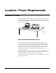
Location / Power Requirements Location of Printer The printer weighs approximately 80 Lbs. (~37Kg) and requires a table of sufficient quality and strength to handle this load while the printer is operating. PAXAR recommends an industrial type worktable having the approximate dimensions of 96" wide to 30" deep to 32" high. Recommended Workstation Layout. The location of the PAXAR 545 printer should be based on human factors.
AC Power Line PAXAR requires that the electric service be 10 Amps @ 115VAC or 10 Amps @ 230VAC. This will allow the computer and any additional support or service equipment to be plugged into the same service. Any electrical service which is supplying a PAXAR printer or peripheral equipment connected to a PAXAR printer should follow standard electrical code practices including proper grounding and neutral requirements.
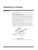
Unpacking / Inventory Unpacking The PAXAR printer is shipped in 2 large cardboard boxes, of which one may be difficult to move by hand. DO NOT REMOVE THE PRINTER FROM THE BOX OR UNPACK IN THE SHIPPING / RECEIVING DEPARTMENT. NOTE: Unpacking in the shipping / receiving department is not recommended for the following reasons. First: The cardboard carton in which your PAXAR printer was shipped allows the printer to be moved with a forklift, or handcart.
Inventory of Components The following list shows the additional parts (pieces) which should be included in your PAXAR 545 shipping containers. If anything is missing, notify PAXAR immediately - in the U.S.A. at 570-888-9116. In other countries please contact your local PAXAR supplier. - PAXAR 545 "User's Manual" - Quick-disconnect power cord - Serial communications cable & converter. - Stacker assembly - One or two print modules as ordered.
Product Description Printer Description The PAXAR model 545 ink jet printer is an electronic printer that can print on fabric rolled tape. The printer interfaces to a computer or a main frame system thus allowing electronic data input or even custom design of labels with PAXAR’S “Formatter / PcMate Plus" program. This printer can generate a complete label printed on one or two sides.
Printer Specification Print method: Narrow web ink jet one or two sided print – Single color only – 2/0 Future Label Size Max: up to 1.5” (38.1mm) web x up to 3.5” (88.9mm) feed - cut and stacked Speed – 4” (101.6mm), 6” (152.4mm) or 8” (203.2mm) per second Up to 6" (152.4 mm) feed w/ rewind Min: .5” (12.7mm) web x .625” (15.9mm) feed Print Area Max: up to 1.36" (34.54mm) web x up to 5.85" (148.5 mm) feed Min: No restrictions Resolution 185.3 DPI across the web x 192.
Other Features - Downloading of information while printer is operating - Sequenced Fields (Printer installed fonts) - Time / Date Stamping (US or European format) - Operator adjustable: print positions, cut position, baud rate - Error Detection of: fabric out, splice, ink out, full stacker, stacker jam - Display: labels left to print in a batch, batch ID, total life inches, total life cuts - Self Diagnostics - Missed sense mark detection and correction (Future) - Slot, Notches, Hole or Reflective registrat
Printer Assembly Fuse Configuration The main fuse(s) on the Paxar 545 are located inside the AC entry. The entry has a fuse drawer that holds the fuse(s) and selects the appropriate line voltage. If the voltage in the window DOES NOT match the AC line amplitude intended to be supplied to the printer, DO NOT plug the power cord in. Reconfigure as follows: 1) Using a flat blade screwdriver, open the AC entry by lifting the tab just above the voltage indicator window. AC Entry 2) Remove the red fuse drawer.
Configuration Number Two: Line voltage within the range of (See 230VAC Fuse Placement) 180 - 265VAC @ 50 - 60Hz 1) Install two 990757 6.0A 250V Fast Acting 5 x 20MM NOTE: The fuse jumper must be removed to install both 5 x 20mm fuses. 115VAC Fuse Placement Placement 230VAC Fuse The fuses must be between points A and B as shown, not B and C. 5 X 20MM Fuse Placement 5) Reinsert the fuse drawer into the AC entry with the desired voltage up.
P.C. Board Identification D C A – Mother Bd. (371170) - Horizontal on bottom of printer B – Head Driver Bd. (341106) - AT Slot 1(From Rear Of Printer) C – Memory Card Bd. (350016) - AT Slot 4 D – Thermal Control Bd. (371105IJ) - AT Slot 2 E – Front Panel Bd.
Inserting a PCMCIA Card A PCMCIA card can be used to store fonts, logos, and operating system upgrades. To insert the card, make sure that the manufacturer’s name is facing the front of the machine. Insert the card so that the end with the holes goes in first. Slide the card in until it reaches the back of the slot and the eject button pops out. To eject the card push in the eject button and then pull the card out. Some machines will ship with a double slotted card option.
Print Module Insertion and Removal CAUTION: Turn off the power to the printer before removing or inserting the print module. Hot swap of the print module has been built into the design. However, a dirty connector from ink etc could prevent it from protecting the head. Therefore, we recommend that all print module removal and replacement be done with the power off. NOTE: An ink cartridge must not be present in the print station before a print module can be installed or removed.
Print Module Handling CAUTION: Do not lay the print module flat on the sides, back, or front if removed from the printer. The unit must stand on end as shown below. Installing the Stacker Remove the stacker from the separate packaging. Remove the packaging from around the stacker and save with the rest of the printer packing supplies. Swing open the top cover to the printer.
Install the stacker up-right rails. Remove one of the spring-loaded screws. Insert the spring-loaded screw through the mating hole in the up-right rail assembly. Thread the spring-loaded screw into the mounting block. Repeat the above procedure for the other rail. Remove the spring-loaded screw and washer from the top of the inner stacker rail. Place the threaded stud into the slot of the outer rail and reattach the washer, spring and nut.
Cable Installation Stacker Cable There is a cable with a connector leading from the back of the stacker that plugs into a socket on the TCB (refer to the P.C. Board Identification section in this manual). The socket and plug are polarized. Rotate the plug until the polarized keyway and socket align and push the stacker connector into the socket. PC Interface Cable The 545 requires a 9-pin RS-232 cable which is provided with the printer. If the cable was not found it can be ordered from PAXAR - (Part no.
Installing the Applications Software The software to drive the Paxar family of printers is covered in separate documentation. The "PcMate Plus / Formatter " software to create formats on site for the Paxar 545 printer is a Windows application. The original "Selfform" will not support the 545. The new "PcMate Plus / Formatter " package is capable of creating formats for all Paxar control printers. Version 3.16.3 or higher is needed.
Printer Operation / Adjustments Installing and Removing Ink Cartridges CAUTION: NEVER INSERT YOUR HAND IN THE INK CARTRIDGE SLOTS AS THE PRINT MODULE NEEDLES ARE UNPROTECTED WHILE THE PRINT MODULES ARE IN THE PRINTER. The individual ink cartridges are color specific and are identified accordingly. To achieve maximum performance from the 545 the color of a print module may not be changed. Changing the color on a print module may contaminate the head.
3) Remove the ink cartridges by pulling them straight out from their current position.
Adjusting the Unwind Before loading fabric for the first time and anytime the fabric width changes - the unwind position must be adjusted - as the 545 is a center justified machine. • Loosen the unwind back plate locking thumbscrew A. • Rotate the back plate B clockwise to increase or counter clockwise to decrease the web width until the desired width is indicated on scale C. • Retighten the locking thumbscrew.
Threading Diagram • Open the hinged cover to the printer and thread the fabric through the splice / fabric out sensor (B drawing two), the active unwind, the barrel rollers, the head guards (A drawing two), the feed module, the knife, and then the stacker as shown.
B A Once the machine has been threaded and is pulling fabric from the supply roll the active unwind will automatically sense the tension of the fabric and adjust the pull off speed accordingly. This will result in a loop in the fabric under the active unwind sensor of about .250” as shown below. .
Web Guide Adjustment The Paxar 545 printer has been designed with crowned rollers to maintain center tracking. The only web guides in the printer are located on the active unwind block. These web guides are adjustable without the use of tools. The only other web width adjustment is the stacker up-right rails (refer to the Stacker Label Width Adjustment). Users Manual Model 545™ • To increase the web guide width, turn the adjustment knob counter-clockwise.
• Open the feed roller by turning the feed lever counterclockwise. • Once the fabric is beyond the last roller - continue straight into the feed rollers, through the knife module and then through to the stacker belts. You will need to lift the pre-feed rollers between the feed and knife in order to push the fabric through the knife. • After the fabric is pulled through the knife, continue feeding through to the stacker belts.
Stacker Position Adjustment • Once the web has been centered in the printer or it has stabilized from running, confirm that equal numbers of belts exist on either side of the fabric, and that the spacing to the nearest belt is the same on each side. This is achieved by loosening the stacker mount screw and moving the stacker forward or back accordingly. Stacker Label Width Adjustment • Users Manual Model 545™ Slide the left and right spring loaded upright rails to the desired position.
Stacker Label Length Adjustment • Loosen the “T” head thumbscrews on either side of the upright base. • Slide the entire base to the desired position so that the cut label hangs over the last belt roller approximately ¼” (6mm) Stacker Angle Adjustment • Turn the lock knob counter-clockwise to allow the stack end of the stacker to rotate. • Once the stack is so that the stacker rails are approximately 5° to 30° off horizontal, tighten the lock knob by turning it clock-wise.
Stacker Full Level Adjustment Users Manual Model 545™ • To change the height at which the machine will stop, first loosen the plastic thumbscrew located on the stacker upright and slide it up or down. • Once the desired stop level is reached retighten the thumbscrew. • Do not bring the thumbscrew in contact with the top of the slot. The thumbscrew must be able to move up approximately 3/16” for the switch to be activated and stop the printer.
Replenishing Fabric at End of Roll • The PAXAR 545 has been designed so that the fabric can be replenished quickly. • Cut the fabric from and remove the spent fabric roll core. • Place a new roll on the unwind and adhere the end of the last roll still threaded in the printer to the leader of the new roll. Make sure you have determined the orientation to prevent any twisting in the fabric.
Print Head Operation Each print module consists of two print heads mounted one on each side of a swing arm. Through an electronic delay the two heads form a single print line. The arm has two positions, the parked position and the print position. Upon the start command the heads are rotated 90 degrees to the print position, and at the stop command the heads are retracted back to the parked position where head maintenance can take place if needed.
Printer Setup From time to time it may be necessary or desirable to reset the printer to a known state of print / cut. The following procedure can be used to make the necessary changes. Only adjust the adjustments that are needed in the order that follows; 1) Clean the machine as needed. 2) Check and adjust the unwind and web guides as needed for the fabric width that is loaded on the machine.
-20 +20 8) On the front panel adjust the PRINT OFFSET STATION 1 to produce one straight continuous feed print line on the back of the label. -20 +20 9) On the front panel adjust the PRINT OFFSET STATION 2 to produce one straight continuous feed print line on the front of the label. -20 +20 10) On the front panel the CUT POSITION should be set to 0, as this is a non-sense mark label.
-10 +10 11) On the front panel adjust STATION 2 DOT SHIFT to cause station 2’s web print line to be directly over station 1’s web print line. -16 +16 Sensor Calibration The optical sensors used to detect error conditions in production can be calibrated without the use of a multi-meter via the front panel. One may need to be calibrated if it has just been replaced or put into service. Refer to the Front Panel Mode Descriptions under the Control Panel Operation section.
Control Panel Operation Control Buttons Start - Starts the printer. - ON LINE light must be GREEN. (Batches downloaded to be printed) - If “Stopped For Splice” error condition exists: Fabric will be advanced until the splice is beyond the print stations. Labels between the heads and knife will be reproduced and stacked as finished labels. Feed - FEED and START must both be used. - Feed will stop when the buttons are released. - Labels between the heads and knife will be cut and stacked as finished labels.
- Fabric moves through with test pattern printing. Stop - The stop button will stop the printer at the end of the current label being printed. Indicator Lights The Paxar 545 has three Indicator lights. These lights are used along with the LC display to tell the operator the current status of the printer. On Line OFF - Has not been powered on. - Is in it's power - up sequence. - Failed the system test. After Power up Sequence: - Printer is running. ORANGE - System is operational.
mark hole. - Flashing light while the printer is running, - the sensor is in-line with the registration HOLES. ORANGE = REFLECTIVE SENSOR - Flashing light while the printer is running, - the sensor is in-line with the registration PRINTED MARKS. Error ORANGE - System inter-lock triggered - see display for error. LCD Display The LCD display is a 2 line, 24 character, with back lighting feature for easy readability. The first line of the display in most cases will be a prompt or question.
Front Panel Menu Map Ready For Batches Î Print / Cut Positions Î Ð → Print Checkout Format Print Head Cleaning Proc Î Ð → Clean Station 1 Calibrating Sensors Î Ð → Hole / Slot In Sensor Life Counts / Versions Î Feature Setup Ð → Label Counter (Re settable) Î Ð → Cutter Enabled / Disabled Verifier Setup Ð → Print Verifier History Ð Ð Ð Ð Ð Ð Print Position Station 1 Clean Station 2 Hole / Slot Not In Sensor Total Labels Produced Emulation Mode: Print Verifier Setup Ð Ð
Front Panel Power Up / Home Screens POWER UP (DIAGNOSTICS TESTS) D I A G N O S T I C T E S T 1 This screen is displayed while the Front Panel is initializing and waiting for the Thermal Control Board (TCB) response. While this screen is displayed the code will check the functionality of the LED's and the display. Each state of the LED's will be checked - (orange, green, amber and off).
HOME SCREEN R E A D Y 5 4 5 F O R B A T C H E S OR B A T C H P C L 0 0 1 I D Q U A N T I T Y 1 0 When the printer is powered up and all initializations are complete, if there aren’t any Batches to print, the "HOME" screen will be "READY FOR BATCHES" and the printer model number. When there are Batches to be printed, the "HOME" screen will be the "BATCH ID QUANTITY” screen. The Batch ID / Batch Qty screen displays the currently cutting batch ID and labels remaining to be cut.
Pressing the MODE / Down Arrow key will take the user to the various mode screens listed below (Refer to the Front Panel Mode Descriptions section in this manual). Pressing the EXIT / Up Arrow key at any time will take the user back to the "HOME" screen.
Front Panel Mode Descriptions There are six (6) main mode levels, which are selected and modified using the following function keys: Use the MODE ↓ key to move through the main mode screens shown below: PRESS ENTER FOR PRINT / CUT POSITIONS PRESS ENTER FOR PRINT HEAD CLEANING PROC PRESS ENTER FOR CALIBRATING SENSORS PRESS ENTER FOR LIFE COUNTS / VERSIONS PRESS ENTER FOR FEATURES SETUP PRESS ENTER FOR VERIFIER SETUP Use the EXIT ↑ to move back to the HOME screens.
PRINT / CUT POSITIONS P R E S S E N T E R F O R P R I N T / C U T P O S I T I O N This screen follows the "BATCH ID / BATCH QTY" screen if there are batches to be printed, otherwise it follows the "READY FOR BATCHES / MODEL" home screen. Pressing ENTER will take the user to the "PRINT / CUT POSITIONS" screens. Pressing the MODE / Down Arrow key will take the user to the "PRINTHEAD CLEANING PROC" screen. Pressing the EXIT / Up Arrow key will take the user back to the "HOME" screen.
P R I N T P O S I T I O N V A L U E : ± X X N E W S T A T I O N 2 V A L U E : ± Y Y This screen follows the "PRINT POSITION STATION 1" screen. This screen allows the print position of station 2 to be adjusted in the feed direction. The buttons are used to change the new print position value. The value is displayed in a positive / negative format. The value ranges for XX and YY can be from a -99 to a +99. Pressing ENTER will change the VALUE to the NEW VALUE.
C H A N G E C U T V A L U E : ± X X P O S I T I O N N E W V A L U E : ± Y Y This screen follows the "PRINT OFFSET STATION 2" screen. This screen allows the cut position to be adjusted on sense mark formats. The buttons are used to change the new cut value. The value is displayed in a positive / negative format. The value ranges for XX and YY can be from a -10 to a +10. Pressing ENTER will change the VALUE to the NEW VALUE.
P R E S S E N T E R F O R C L E A N I N G S T A T I O N 2 This screen follows the "CLEANING STATION 1" screen. This screen allows the user to initiate a cleaning cycle for station 2. Pressing ENTER will initiate a cleaning procedure on station 2 based on it’s default cleaning level setting. Pressing the MODE / Down Arrow key will take the user to the "CHANGE DEFAULT CLEANING LEVEL STATION 1" screen. Pressing the EXIT / Up Arrow key will take the user back to the "HOME" screen.
CALIBRATE SENSORS P R E S S E N T E R T O C A L I B R A T E S E N S O R S This screen follows the "PRINT HEAD CLEANING PROC" screen. Pressing ENTER will take the user to the "CALIBRATE SENSORS" screens. Pressing the MODE / Down Arrow key will take the user to the "LIFE COUNTS/VERSIONS" screen. Pressing the EXIT / Up Arrow key will take the user back to the "HOME" screen.
B O T R E F L O V E R V A L U E : 0 0 0 N E W M A R K V A L U E : 0 0 0 This screen follows the "TOP REFL NOT OVER MARK" screen. Place the fabric over the bottom reflective sensor so that the reflective mark is over the sensor and when NEW VALUE is at the highest value press ‘Enter’. Pressing the MODE / Down Arrow key will take the user to the "BOT REFL NOT OVER MARK" screen. Pressing the EXIT / Up Arrow key will take the user back to the "HOME" screen.
S T O C K O U T V A L U E : 0 0 0 N O T N E W B L O C K E D V A L U E : 0 0 0 This screen follows the "STOCK OUT BLOCKED" screen. Reposition the fabric so that a splice is within the sensor site path and when NEW VALUE is at the lowest value press ‘Enter’. Pressing the MODE / Down Arrow key will take the user back to the "HOLE / SLOT IN SENSOR" screen.
C O N T R O L L E R X X X X X V E R S I O N This screen follows the "TOTAL INCHES OF STOCK" screen. This screen shows the operating system version for the controller (TCB). Pressing the MODE / Down Arrow key will take the user to the "IMAGER VERSION" screen. Pressing the EXIT / Up Arrow key will take the user back to the HOME screen. I M A G E R X X . X X V E R S I O N This screen follows the "CONTROLLER VERSION" screen. This screen shows operating system version for the imager (AT).
N E W L A N G U A G E : L A N G U A G E : X X X X X X Y Y Y Y Y Y This screen follows the "EMULATION MODE" screen. This screen allows the front panel display language to be changed. Use the keys to move between the supported languages on the printer. Any number of front panel languages can be stored on the optional PCMCIA card (dependent on available space). If no additional languages other than the default are available on the printer XXXXXX and YYYYYY will be the same value.
VERIFIER SETUP P R E S S E N T E R F O R V E R I F I E R S E T U P This screen follows the "FEATURE SETUP" screen. Pressing ENTER will take the user to the "VERIFIER SETUP" screens. Pressing the MODE / Down Arrow key will take the user back to the "PRINT / CUT POSITIONS" screen. Pressing the EXIT / Up Arrow key will take the user back to the "HOME" screen. P R E S S P R I N T E N T E R T O V E R I F I E R H I S T O R Y This screen is the first screen under "VERIFIER SETUP".
Maintenance Print Module Handling Warning Print heads contained in the print modules can be damaged easily, and are subject to premature failure if not properly handled. Careful handling must be exercised so as not to damage the nozzle plate. Please follow the procedures carefully to help ensure print module life and print quality.
Print Module Replacement / Height Adjustment CAUTION: Turn off the power to the printer before removing or inserting the print module(s). DUE TO THE TOLERANCES IN THE PRINT MODULES AND OF THE PRINT HEADS THEMSELVES, THE ENTIRE PRINT MODULE MUST BE REPLACED - ONCE A PRINT HEAD HAS REACHED ITS END OF LIFE. 1) Remove the ink cartridge from the printer in order to remove the print module.
Print Head Swing Arm Stop Adjustment If a gap or overlap appears in the image on the front or back of the label it may be necessary to adjust the print head swing arm stop screw A for that print station. A Using a 5/64” hex key - adjust screw A for the station needing the adjustment. Rotating the screw counter clockwise will decrease the overlap or increase the gap. Rotating it clockwise will decrease the gap or increase the overlap.
Automated Print Head Cleaning Before performing the Automated Print Head Cleaning procedure check the print head guard slots for any foreign objects that maybe deflecting or blocking the ink while in flight. Automated Print Head Cleaning is performed on operator command from the front panel. From time to time it may become necessary to perform a cleaning routine to purge air or clear clogged print head nozzles. There are two cleaning levels to choose from for each print station.
Manual Manifold Seal Cleaning CAUTION: The print head nozzle plates are very delicate, use extreme care not to contact the print head nozzle plates while the print heads are in the print position. Use nothing other than foam tips with minimal pressure while cleaning the manifold seals. From time to time depending on the amount of dust and debris in the printing environment the manifold seals may need to be cleaned by wiping.
Cleaning • Take a new foam tip swab (not a cotton swab) and clean any excess ink and debris from both of the manifold seals for each print module present as shown. • Use a wiping action across the seals to avoid pushing any debris down into the manifold seal holes. • 60 • Maintenance When done cleaning, press the “NO (→)” button to swing the (active) print station(s) to the home / park position.
General Machine Cleaning The machine should be cleaned every eight hours of use or as needed. With the exception of the print heads and the optical sensors, the machine can be cleaned using an alcohol base solution. Simply apply a liberal amount of alcohol to a clean rag and wipe down the machine components starting at the unwind and ending at the stacker. Printheads Refer to the Automated Print Head and Manual Manifold Cleaning sections for cleaning the print heads.
Lubrication Procedure General The 545™ series printers are factory equipped with pre-lubricated bronze bearings that do not require lubrication. The one exception is the rub cams on either end of the rotary knife. Periodic cleaning of the printer and removal of dust will greatly enhance the length of the time the printer will function. Cam - Lubrication Procedure 1) Clean any dust and residue from cams (using alcohol or other suitable solvent) as needed, or approximately every 100,000 cuts.
Changing Stacker Belts FULL STACKER CONNECTOR 8-32 CAP SCREWS FIGURE 1 1. Remove stacker rail assembly by removing full stacker connector and (2) 8-32 cap screws from stacker mounting plate.
RIVETS JAM SENSOR HARNESS SNAP RING FIGURE 2 2. Remove upper conveyor roller assembly by removing jam sensor harness connector, snap-rings and rivets. REMOVE LOOSEN 6-32 SET SCREWS 8-32 SCREW (SEE ITEM 5) DRIVE BELT COVER FIGURE 3 3. Remove the drive belt cover. 4. Loosen 6-32 set screws in ends of main drive roller.
5. Insert an 8-32 screw into the threaded hole in the front side of the roller pin and remove the pin. (See figure 3) 6. Remove the thumbscrew on the front side of the stacker rail base and let the square nut on the underside fall out. Loosen the thumbscrew on the far side to allow slack for the belts to slide on. (See figure 3) FIGURE 4 7. Pull the drive away from the frame enough to allow the roller / belts to be lifted out of the frame.
SMALL DUAL DRIVE BELTS (SEE ITEM 8) FIGURE 5 8. Remove small dual drive belts from one side of front roller to allow assembly of new belts. 9. To re-assemble, reverse procedure above.
Electrical Trouble Shooting Power Up / Sign On / Communications Problem Printer fails to power up. Probable Cause Corrective Action 1) Incorrect power amplitude. 1) Confirm that the AC entry is configured for the line voltage intended to be applied to the printer. Failure to do so can damage the printer's internal power supplies. 2) Lack of power to printer. 1) Check that both ends of the power cord are plugged in securely. 2) Confirm that the outlet the printer is plugged into has power.
Problem Probable Cause Front panel does not complete 1) One or more PC board(s) diagnostics test 2. unplugged from the Mother Board. Printer does not receive batches. Corrective Action 1) Power off and remove the power cord from the AC entry. Remove the back cover and reseat the offending board. 2) PCMCIA cartridge not inserted correctly in PCMCIA slot. 1) Insert a PCMCIA cartridge with the arrow up and towards the front of the printer so that the ejector button pops out.
Fabric Advance Problem Fabric does not advance when the start button is depressed. Users Manual Model 545™ Probable Cause Corrective Action 1) No batches to be printed. 1) Download batch (if batch downloaded uses the same format as a previously downloaded batch the printer with start automatically). 2) An interlock condition exists. 1) Determine the number and type of interlock(s) by reading the front panel display.
Print Problem Probable Cause Printer advances fabric but does not print. 1) If sense mark format fabric registration sensor miss aligned. 1) Adjust sensor position so that the sensor light on the front panel flashes as a sense mark / hole passes under the sensor. 2) Print station(s) inactive. 1) Using the front panel - activate the needed print station(s). 3) Print module not fully engaged. 1) Remove the ink cartridge and reinsert the offending print module. 4) Print module void of ink.
Problem Voids in print image in the feed direction. Printer continually stops with an erroneous interlock condition. Probable Cause Corrective Action 1) Nozzles clogged or void of ink. 1) Enter the Print Head Cleaning Mode and clean the print module. 2) Print head swing arm stop misadjusted. 1) Adjust the swing arm stop position as needed to prevent any gap or overlap in the center of the image. 3) Faulty print head.
Mechanical Trouble Shooting Fabric Problem Probable Cause Fabric will not roll or jumps 1) Incorrect adjustment of unwind web guides Corrective Action 1) Be sure fabric roll is as flat as possible and does not extend over core. 2) Adjust the web guides to touch the fabric roll without pinching the core. Fabric jams in bridge blade rollers or knife area. 1) Knife mounted bridge blade too close to stationary bridge blade.
Ink Problem Probable Cause Corrective Action Probable Cause Corrective Action Print Problem Users Manual Model 545™ Mechanical Trouble Shooting • 73
Sensor Locations A – Fabric Out / Splice Sensor – Detects when the fabric is depleted or a splice is present. B – Active Unwind Loop Sensor – Detects the fabric to maintain a predetermined amount of slack in the active unwind. C – Jam Sensor – Detects a jam in the stacker. D – Full Stacker – Detects when the stacker is full.
Non-volatile Memory Reset It may be necessary from time to time to reset the non-volatile SRAM in the machine. This can be done by using the DIP switch setting of the TCB at power up. Use the following steps to perform this function: 1) Power off the machine. 2) Change switch number 2 from its present position. 3) Power on the machine, wait at least 30 seconds, then turn power off. 4) Change switch number 2 back to its original position.
Electrical Drawings Printer Wiring 76 • Electrical Drawings Users Manual Model 545™
Electrical System Schematic 115V 230V HARNESSED 24V POWER SUPPLY 341116 AC ENTRY 341111 CONN 6 LINE LINE CORD 181134 A L B N GROUND 115V STRAP NEUTRAL C 115V STRAP D G FINISHING INTERFACE BOARD J7 341107 351141 LOOP SENSOR 341137 CONN 3 SPLICE/STOCKOUT SENSOR HARNESSED 371133 J1 SYSTEM HARNESS 341139 RETURN FEED OPEN SWITCH 191120 OPTIONAL PCMCIA BOARD 351181 L +12V N ACTIVE UNWIND MOTOR CONN 4 +24V 115V OPERATION ONE 6.25A 250V 1/4 X 1 1/4 FUSE 990689 230V OPERATION TWO 6.
Motherboard Power Connectors The power supply connector on any PC / XT or PC / AT compatible motherboard is made up of dual six-pin male connectors. Two female connectors from the power supply plug directly onto these male connectors. The following diagrams illustrate the proper method of attaching the connectors.
Appendix A Error Messages On the Machine's detection of error(s), the display will show the first error encountered and allow the displaying of any other errors with the keys, which will "Scroll" through additional errors if any. XX is the total number of errors at the time of error detection.
Appendix B Chip Upgrade Positions / Jumper Settings JP 2 R59 R60 R62 U 14 D30 D6 D18 D5 D35 C 20 C10 C13 R31 R29 C12 U6 U7 U8 U1 J4 U16 A1 U5 J5 C17 C 15 C18 + C7 R64 C5 J6 A1 A45 A58 C8 JP1 C11 R5 C 19 C 21 U15 U10 U 12 Head Driver Board P/N 341106 (Use chip removal tool P/N. 351156 for square I.C removal) HEAD DRIVER BOARD, Upgradeable software I.C.'s include U1, U14, U17.
J11 J12 R 39 J14 R40 J7 J1 J10 J13 J5 L2 1 D55 C82 C69 D 36 U25 C63 R 14 U 23 U21 C34 1 F2 C97 U12 U13 R15 C 96 C 95 A 31 + C 93 + C 35 C94 U16 + C 33 J3 R57 R58 U43 C31 U9 C 28 18 U4 C51 U3 SN.
Front Panel Board P/N 511108 (Use chip removal tool P/N. 351156 for square I.C removal) FRONT PANEL BOARD, Upgradeable software I.C.'s include U1. PLCC CHIPS align angled corner of chip with angled corner of socket that is counter clockwise to the arrow.
Appendix C Ink Management / Shelf Life The liquid ink contained in the ink cartridges has a shelf life of one year. It is therefore recommended that any inventory supply be rotated on a regular basic to prevent exceeding its expiration date. Caution: Expired ink may damage print heads. Check the expiration date on the cartridge label. Do not use expired ink. Contact your Paxar representative for instructions on returning expired cartridges.
Appendix D Knife MFG Guidelines Solenoid Trigger Setting +.000 -.020 1. After the clutch and actuator is mounted to the knife, attach the solenoid assembly to the inside support using two 6-32 x 3/8 cap screws, flat washers, and lock washers. Make sure the plunger moves freely and does not bind. Motor and faceplate must be mounted also. 2. Check the gap between the actuator and the top of the pin on the clutch as shown in drawing. The plunger should be pushed in to make the measurement.
Appendix E Material Safety Data Sheet ======================== SECTION I - GENERAL INFORMATION ======================== PRODUCT NAME: IJ1111 MANUFACTURER'S NAME: MANUFACTURER'S ADDRESS: DATE PREPARED: September 28, 1998 PAXAR CORPORATION, Systems Group PAXAR CORPORATION 1595 Cedar Line Drive Rock Hill, SC 29730 EMERGENCY TELEPHONE NUMBER: (803) 324-2486 CHEMICAL NAME: SYNONYMS: FORMULA: Pigmented liquid ink None Mixture ================= SECTION II - HAZARDOUS INGREDIENT INFORMATION =================
=========================== SECTION V - REACTIVITY DATA =========================== STABILITY: Stable INCOMPATIBILITY: Strong oxidizing agents HAZARDOUS DECOMPOSITION PRODUCTS: None known to exist. HAZARDOUS POLYMERIZATION: Will not occur.
======================== SECTION VIII - CONTROL MEASURES ======================== RESPIRATORY PROTECTION:None is specifically recommended for handling this product. VENTILATION: None required. Respiratory exposure to material in aerosol form should be avoided. EYE PROTECTION: None required. Avoid contact with eyes. Use glasses or face shield when transferring large quantities. SKIN PROTECTION: None required. Avoid contact with skin. Use gloves when transferring large quantities.
Assembly Drawings Users Manual Model 545™ Assembly Drawings • 89
Frame Assembly Cover Drawing 16 16 16 3 13 17 12 13 4 14 12 12 17 15 18 7 7 18 2 14 7 14 19 6 7 10 10 11 14 8 1 10 14 9 10 8 5 9 8 9 14 14 90 • Assembly Drawings Users Manual Model 545™
Frame Cover Parts List Item 1 2 3 4 5 6 7 8 9 10 11 12 13 14 15 16 17 18 19 Users Manual Model 545™ Part # 341203 341206 341202 341204 341201 341216 990053 341210 991079 341215 341111 511209 990051 991054 990456 990055 341209 990023 341213 Description 560 Base Pan Frame, Upright Back Cover Hinged Cover Front Cover Mounting Block, Triangle 8-32 x ¾ Cap Screw Feet, 1 ½” Dia. Rubber 8-32 ½ Thread Forming Screw 10-32 x ½ Sem Screw AC Entry With Switch Bracket, Angle 8-32 x 3/8 Cap Screw 8-32 x 3/8 Btn. Hd.
Frame Assembly Drawing 92 • Assembly Drawings Users Manual Model 545™
Frame Parts List Item 1 2 3 4 5 6 7 8 9 10 11 12 13 14 15 16 17 18 19 Users Manual Model 545™ Part # 341206 341128 345046 345108 341203 990082 345037 345043 345038 991115 990102 990091 990081 990243 143027 341132 990448 991033 345022 Description Frame, Upright Assembly, Print Module Cable Chase Way, Trailing Actuator, Shroud Lock #10 Lock Washer 10-32 x 5/8 Cap Screw Knob, Chase Mount, Chase Bar Bar, Chase ¼-20 x 1 ¼ Flt. Hd.
Sub - Frame Assembly Drawing 94 • Assembly Drawings Users Manual Model 545™
Sub - Frame Parts List Item 1 2* 3 4 5 6 7 8 9 10 11 12 13* 14 15* Part # 341206 343045 343044 343041 343040 343102 343103 990023 991125 991137 990145 990121 990016 343039 343048 Description Frame, Upright Shaft, ABC Spindle Spacer, Outer Race Standoff, Partition Short 10-32 x 3/8 Flat Head Screw Bracket, Adjuster Standoff, Adjuster 6-32 x ½ Flat Head Screw 8-32 x 3/16 SK Set Screw Soft Tip 3-48 x ½ Cap Screw ¼ Lock Washer ¼-20 x 5/8 Cap Screw 6-32 x 3/5 Cap Screw Shaft, D-G Spindle Bearing, Ball Spindle
Power Unwind Assembly Drawing 96 • Assembly Drawings Users Manual Model 545™
Power Unwind Parts List Item 1 2 3 4 5 6 7 8 9 10 11 12 13 14 15 16 17 18 19 Part # 341206 343135 990486 343120 343122 991067 343150 343193 990329 343208 371133 343118 343117 154020 343116 990273 343115 343141 343126 Description Frame, Upright Ass’y, Bracket Unwind E-ring 3/8 Shaft, Capstan Stud, Barrel Idler 8-32 x 5/16 Knuckle Cup Set Roller, Drive Ass’y Spindle Idler E-ring 7/32 Bracket, Sensor Mount Sensor Harness Shaft, Web Guide Guide, Web Outside Web Guide Shaft Guide, Web Inside #10 Bellville Wash
Unwind Support Assembly Drawing 98 • Assembly Drawings Users Manual Model 545™
Unwind Support Parts List Item 1A 2A 3A 4A 5A 6 7 8 9 10 11 12 13 Part # 990058 105023 143016 990371 143020 343204 343225 990894 343202 343222 990105 990056 990066 Description 8-32 x ¼” Set Screw Knob 3” Unwind Core ¼” Collar Stud, Unwind Core Bracket, Arbor Disk Assembly, Collar Clamp 10-32 x ¼” “T” Thumb Screw Shaft, Unwind Arbor Knob, Adjustment 10-32 x ¼” Set Screw 8-32 x ½” Flat Head Screw 8-32 x ¼” Button Head Screw Qty 1 1 1 3 1 1 1 1 1 1 1 2 1 Item 14 15 16 17 18 19 20 21 22 23 Part # 343207 34
Unwind Nip Roller Assembly Drawing 6 5 1 11 3 7 4 8 2 9 10 9 100 • Assembly Drawings Users Manual Model 545™ 8
Unwind Nip Roller Parts List Item 1 2 3 4 5 6 7 8 9 10 11 Users Manual Model 545™ Part # 343192 343134 343131 343130 990051 343195 343133 990325 990052 990329 343142 Description Post, Snubber Arm, Unwind Nip Cradle, Unwind Nip Anchor, Nip Spring 8-32 x 3/8 Cap Screw Assembly, Roller, Nip Shaft, Nip Roller “E”-Ring 3/16 8-32 x ½ Cap Screw “E”-Ring 7/32 Spring, Unwind Ext. Qty.
Unwind Snubber Assembly Drawing 102 • Assembly Drawings Users Manual Model 545™
Unwind Snubber Parts List Item 1 2 3 4 5 6 7 8 9 10 11 12 13 Users Manual Model 545™ Part # 343128 343162 343192 343143 343144 343145 343139 990329 341137 989985 990000 343227 990019 Description Carrier, Snubber Bracket, Snubber Comb Post, Snubber Stud, Snubber Spring Spring, Extension, Snubber Anchor, Snubber Spring Roll Pin .156 x 1.
Print Module Assembly Drawing 104 • Assembly Drawings Users Manual Model 545™
Print Module Parts List There are no parts in the print module that can be changed by the user. If a print module becomes defective, it will have to be sent back to the factory for rebuilding. The same module is used in both the right and the left print stations. The part number for the complete assembly is 345090.
Cartridge Support Deck Assembly Drawing 106 • Assembly Drawings Users Manual Model 545™
Cartridge Support Deck Parts List Item 1 2 3 4 5 6 7 8 9 10 Part # 346202 343042 990038 197312 990019 989974 346212 346204 346201 990240 Description Bracket, Left Enclosure 6-32 SEM x 3/16” Screw 6-32 Hex Nut Spring, Cam 6-23 x ¼” Button Head Screw 8-32 x 5/8” Cap Screw Bracket, Ground Clip Bracket, Ink Support Ink Support 3/32 x ½” Roll Pin Users Manual Model 545™ Qty 1 6 2 2 4 4 2 2 1 4 Item 11 12 13 14 15 16 17 18 19 20 Part # 346206 990225 346205 345105 990015 346208 991058 991114 989976 346203 D
Feed Assembly Drawing 108 • Assembly Drawings Users Manual Model 545™
Feed Parts List Item 1 2 3 4 5 6 7 8 9 10 11 12 13 14 15 16 17 Users Manual Model 545™ Part # 341206 351141 344056K 990081 990728 990017 990037 991073 344051 374028 990065 344053 344052K 244012 344055 354094 989513 Description Frame, Upright Ink Motor Drive Gear, 24T 10-32 x ½ Cap Screw #10 Lock Washer 6-32 x ½ Cap Screw #6 Washer SAE Standoff, 1 ¾, 10-32 THD Fixed Idler Shaft Pulley, 14T PBL FLG, 3/8 I.D. 8-32 x 3/8 Button Head Screw Gear 156T, 3/8 O.D. Idler Shaft Pulley 14T SFL ¼ I.D.
Feed Roller Assembly 1 6 26 7 17 18 2 15 30 8 3 16 12 14 23 25 24 13 4 28 27 3 20 5 9 29 19 15 21 27 20 29 10 11 22 23 12 23 110 • Assembly Drawings Users Manual Model 545™
Feed Roller Parts List Item Part # Description 1 341206 Frame, Upright 2 514001 Shaft, Idler Roller 3 999037 Iglide, .50 x .
Knife Assembly Drawing 112 • Assembly Drawings Users Manual Model 545™
Knife Parts List Item Part # Description 1 197003 #10 Washer 2 197308 Adjuster, Knife 3 197311 Cam, Knife Homing 4 197312 Spring, Cam 5 197313 Plate, Spring Cam 6 357020 Actuator, Knife 7 197317 Compression Spring 8 351123 Knife Solenoid Harness 9 517099 Knife Motor Assembly 10 991067 8-32 x 5/16 Knurled Pt. Set Screw 11 999097 Flg Bushing (Inc.
Stacker Assembly Drawing – Part 1 114 • Assembly Drawings Users Manual Model 545™
Stacker Parts List – Part 1 Item 1 2 3 4 5 6 7 8 9 10 11 12 13 14 15 16 17 18 Part # 348001 348002 348017 990020 990016 348107 989994 378213 378208 378201 378287 378204 378203 224053 188014 990167 990126 348006 Description Frame, Rear Stacker Frame, Near Stacker Support, Pick-Up Roller 6-32 x 3/8 Button Head Screw 6-32 x 3/8 Socket Head Cap Sc. Support, Roller 2-56 x ¼” Socket F.H.
Stacker Assembly Drawing – Part 2 116 • Assembly Drawings Users Manual Model 545™
Stacker Parts List – Part 2 Item 1 2 3 4 5 6 7 8 9 10 11 12 13 14 15 16 17 18 19 20 21 22 23 Part # 348106 348192 348191 348005 990894 928008 348014 378209 990051 991107 999012 378215 378035 990006 990466 990038 184002 358013 990369 358017 990028 990029 188008 Description Plate, Stacker Support Assembly, Rear Stacker Side Assembly, Front Stacker Side Bracket, Rail Side 10-32 x ¾ “T” Thumb Screw “T” Nut #10 Formed Base, Stacker Rail Mount, Stacker Rail 8-32 x 3/8 Cap Screw 10-32 x 5/8 Button Head Screw ¼ x
Rewind Assembly Drawing 118 • Assembly Drawings Users Manual Model 545™
Rewind Parts List Item 1 2 3 4 5 6 7 8 9 10 11 12 13 14 15 16 17 18 Part # 112033 112035 923009 111032 990054 111029 990374 112028 112032 112030 999118 112005 990091 197078 990465 112031 112036 999121 Description Shaft, 6x6 rewind Key, 1/8 x 1/8 x 3/8 10" roll disc Rubber feet 8:32 x 1 cap screw Base 1/2" collar Driven disc Friction disc Drive disc 1/2 x 5/8 x 1 1/4 bushing 28t 1/5p timing belt pulley 10:32 x 1/2 btn hd screw 12t 1/5p timing belt pulley comp.