Owner’s Installation Guide for the Paxton Automotive Novi 1200 Supercharger Dodge Hemi for the Paxton Automotive . 1300 Beacon Place . Oxnard CA 93033 (805 604-1336 . FAX (805) 604-1337 DP/N: 4809650 - v1.
FOREWORD P roper installation of this supercharger kit requires general automotive mechanic knowledge and experience. Please browse through each step of this instruction manual prior to beginning the installation to determine if you should refer the job to a professional installer/technician. Please call Paxton Automotive for installers in your area. © 2005 PAXTON AUTOMOTIVE All rights reserved.
TABLE OF CONTENTS FOREWORD . . . . . . . . . . . . . . . . . . . . . . . . . . . . . . . . . . . . . . . . . . . . . . . . . . . . . . . . . . . ii TABLE OF CONTENTS. . . . . . . . . . . . . . . . . . . . . . . . . . . . . . . . . . . . . . . . . . . . . . . . . . . . . . . . iii RECOMMENDED TOOLS FOR INSTALLATION. . . . . . . . . . . . . . . . . . . . . . . . . . . . . . . . iv PARTS LIST . . . . . . . . . . . . . . . . . . . . . . . . . . . . . . . . . . . . . . . . . . . . . . . . . . . . . . . . .
RECOMMENDED TOOLS FOR INSTALLATION B 2002 Dodge Hemi efore beginning this installation, please read through this entire instruction booklet and RECOMMENDED TOOLS the Street Supercharger System Owner's Manual which includes the Automotive Limited Warranties Program and the Warranty Registration FOR INSTALLATION: form. 1. Factory Repair Manual Paxton supercharger systems are performance 2. 3/8" Socket and Drive Set: SAE & Metric improving devices.
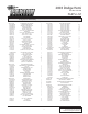
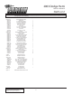
2003 Dodge Hemi Part No. 1201220 PARTS LIST IMPORTANT: PART NO. Before beginning installation, verify that all parts are included in the kit. Report any shortages or damaged parts immediately.
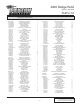
2003 Dodge Hemi Part No. 1201220-P PARTS LIST IMPORTANT: PART NO. Before beginning installation, verify that all parts are included in the kit. Report any shortages or damaged parts immediately. DESCRIPTION QTY 8PN104-010 8N056-060 7E010-075 7P500-078 8N055-050 7J006-093 7C060-016 7U100-055 7P500-078 7P500-026 7U100-044 7A250-050 8N010-130 ASSY SURGE TANK '03 HEMI SURGE TANK #12 SHEET METAL SCREWS 1/2" x 3/4" STR HOSE BARB PLASTIC CAP, SURGE TANK 6mm WASHER, PLATED M6 x 1.
2003 Dodge Hemi Part No. 1201220-P PARTS LIST IMPORTANT: PART NO. Before beginning installation, verify that all parts are included in the kit. Report any shortages or damaged parts immediately.
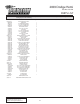
2003 Dodge Hemi Part No. 1201220 PARTS LIST IMPORTANT: PART NO. Before beginning installation, verify that all parts are included in the kit. Report any shortages or damaged parts immediately. DESCRIPTION QTY 8PN104-010 8N056-060 7E010-075 7P500-078 8N055-050 7J006-093 7C060-016 7U100-055 7P500-078 7P500-026 7U100-044 7A250-050 8N010-130 ASSY SURGE TANK '03 HEMI SURGE TANK #12 SHEET METAL SCREWS 1/2" x 3/4" STR HOSE BARB PLASTIC CAP, SURGE TANK 6mm WASHER, PLATED M6 x 1.
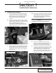
1. COMPONENT REMOVAL Section 1 COMPONENT REMOVAL 1. COMPONENT REMOVAL A. Using a suitable container drain the engine coolant. On the driver’s side of the vehicle at the lower corner of the radiator locate the drain petcock using a 16mm open-end wrench rotate the petcock and drain the coolant. B. Locate the coolant over flow reservoir located on the top of the radiator, loosen the hose clamp securing the large 1" coolant hose and remove the hose from the reservoir.
G. Unclip the 4 clips that retain the top portion of the factory air filter housing and set the housing and rubber duct aside it will not be reused. H. Remove the air filter and lift up on the lower portion of the factory air filter housing and remove it from the air filter support bracket set the lower portion of the housing aside it will not be reused. (See Fig. 1-e.) K. Remove the factory orange silicone ring from the throttle body and set aside. Remove the accessory drive belt. (See Fig. 1-g.) Fig.
2. OIL FEED ASSEMBLY Section 2 OIL FEED ASSEMBLY 2. OIL FEED ASSEMBLY A. Disconnect the factory oil pressure sending unit wire harness from the sending unit. Remove and set aside the factory oil pressure sender located on the passenger of the engine. Using the supplied fitting install the short 1" nipple into the side of the supplied tee fitting. *** NOTE *** Do not use Teflon paste or Teflon tape on this fitting as it may clog the supercharger oil jet and lead to premature supercharger failure. B.
This Page Left Intentionally Blank. P/N: 4809650 ©2004 Paxton Automotive All Rights Reserved, Intl. Copr. Secured 11NOV04 v1.0 03DodgeHemi(4809650v1.
3. OIL DRAIN ASSEMBLY Section 3 OIL DRAIN ASSEMBLY 3. OIL DRAIN ASSEMBLY A. On the passenger side of the oil pan locate the large hump in the oil pan measure down1-3/4" from the lip of the oil pan and make a mark. Center the mark between the two oil pan retaining bolts. (See Fig 3-a.) E. Thoroughly clean the threaded area. Reach inside the oil pan and retrieve any stray chips. Apply a small amount of sealer to the new threads.
This Page Left Intentionally Blank. P/N: 4809650 ©2004 Paxton Automotive All Rights Reserved, Intl. Copr. Secured 11NOV04 v1.0 03DodgeHemi(4809650v1.
4. HEATER HOSE RELOCATION Section 4 HEATER HOSE RELOCATION 4. HEATER HOSE RELOCATION A. Install a supplied 3/8" x 45° street elbow into the front cover of the engine, install the second supplied 3/8" x 45° street elbow into the previously installed elbow. Install the factory hose barb fitting that was removed in Step 1-e and install into the open end of the street elbow. *** NOTE *** Assemble the fittings using Teflon paste to aid in sealing.
This Page Left Intentionally Blank. P/N: 4809650 ©2004 Paxton Automotive All Rights Reserved, Intl. Copr. Secured 11NOV04 v1.0 03DodgeHemi(4809650v1.
5. COOLANT RESERVOIR RELOCATION Section 5 coolant reservoir relocation 5. COOLANT RESERVOIR RELOCATION A. Locate the lower radiator hose. Locate the TEE fitting in the lower radiator hose that the 1" hose attaches measure up approximately 2-1/2" from the tee fitting and cut the upper portion of the hose. B. Locate the three spacers, screws, and washers in the coolant relocation assembly. Raise the coolant reservoir using the spacers and secure with the supplied 6mm screws and washers. (See Fig. 5-a.
This Page Left Intentionally Blank. P/N: 4809650 ©2004 Paxton Automotive All Rights Reserved, Intl. Copr. Secured 11NOV04 v1.0 03DodgeHemi(4809650v1.
6. SUPERCHARGER MOUNTING BRACKET Section 6 SUPERCHARGER MOUNTING BRACKET 6. SUPERCHARGER MOUNTING BRACKET A. Locate the supplied two small supercharger mounting plate support brackets bolts and washers. Assemble the two brackets using the four 5/16" x 18 x 1.0" bolts and washers that are provided. B. Using the supplied support bracket and the supplied 8mm x 120 bolts and 10mm x 130 bolts confirm that the heater hose fittings and hose previously installed clear the support bracket. C.
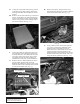
G. Remove the casting flash from the lower mounting location using a file or small disc sander. INSTALL THE 12mm x 100 x 1.75 BOLT THROUGH THE ORIGINAL MOUNTING HOLE IN THE FRONT COVER *** NOTE *** Care must be taken to not damage the machined surface, as this surface is critical to proper mounting bracket alignment. 13mm HEADED BOLT REMOVED IN AN EARLIER STEP CASTING FLASH TO BE REMOVED Fig. 6-e J.
P. Install the supercharger/accessory drive belt using the belt routing diagram provided. Q. Install the supplied 1/8" NPT x –4 fitting into the supercharger oil jet, attach the open end of the supplied braided oil feed line to the –4 fitting previously installed. (See Fig. 6-h.) 90° -4 OIL SUPPLY HOSE AND 1/8 NPT FITTING Fig. 6-f N. Attach the supplied 1/2" supercharger oil drain line and supplied hose clamp to the 3/8" NPT barbed fitting on the supercharger, tighten the hose clamp.
This Page Left Intentionally Blank. P/N: 4809650 ©2004 Paxton Automotive All Rights Reserved, Intl. Copr. Secured 11NOV04 v1.0 03DodgeHemi(4809650v1.
7. AIR INTAKE ASSEMBLY Section 7 AIR INTAKE ASSEMBLY 7. AIR INTAKE ASSEMBLY A. Locate the supplied air filter, formed enclosure, mounting flange, and 1/4"-20 mounting hardware. B. Attach the flange to the air filter enclosure using the 1/4"-20 nuts, bolts, and washers provided. (See Fig. 7-a.) *** NOTE *** The upper mounting tab should be about 1/8" down from the top of the fender. (See Fig 7-x.) F.
Fig. 7-c I. Locate the air intake temperature sensor previously removed, install into the unthreaded bung on the 180° inlet elbow. Locate the air temperature sensor factory plug, strip back the tape to expose the wires and cut the wires approximately 3" from the connector plug. Using the supplied 12" length of wires extend the connector plug to reach the relocated air temperature sensor.
8. FUEL SYSTEM ASSEMBLY Section 8 FUEL SYSTEM ASSEMBLY 8. FUEL SYSTEM ASSEMBLY A. Locate the supplied supplemental fuel supply assembly 4PCH101-001. Assemble the supplied fuel pump to the supplied fuel pump/FMU mounting bracket using the provided adel clamps and 1/4"-20 bolts, nuts, washers as shown in Fig. 8-a.
5/16" fuel hose to the inlet of the FMU and secure using a supplied clamp. Route the open end of the 5/16" fuel hose to the open barb of the TEE fitting, trim the hose for best fitment and secure using a supplied hose clamp. G. Cut the 5/16" fuel hose previously installed from the supplied fuel pump outlet to the factory fuel line, install the supplied TEE fitting at this connection and secure it using two supplied hose clamps.
9. ENGINE CONTROL UNIT INSTALLATION Section 9 ENGINE CONTROL UNIT INSTALLATION ENGINE CONTROL UNIT INSTALLATION E. Locate pin 34 at the C2 plug on the Factory ECU. Cut the tan/yellow wire (Cam Sensor). Connect the tan wire from the PECU to the tan/yellow wire leading to the cam sensor on the factory ECU. Connect the tan/yellow wire from the PECU to the tan/yellow wire leading to the factory ECU plug. F. Locate pin 23 at the C2 plug on the factory ECU. Cut the green/red wire (Map Sensor).
This Page Left Intentionally Blank. P/N: 4809650 ©2004 Paxton Automotive All Rights Reserved, Intl. Copr. Secured 11NOV04 v1.0 03DodgeHemi(4809650v1.
10. CHARGE COOLER INSTALLATION Section 10 CHARGE COOLER INSTALLATION 10. CHARGE COOLER INSTALLATION A. Install a supplied reducer sleeve onto the throttle body, install the aftercooler core into the reducer sleeve and secure with the supplied hose clamps. Install the supplied 2.75" x 2" sleeve onto the discharge of the supercharger and another on the open end of the aftercooler core previously installed. B.
This Page Left Intentionally Blank. P/N: 4809650 ©2004 Paxton Automotive All Rights Reserved, Intl. Copr. Secured 11NOV04 v1.0 03DodgeHemi(4809650v1.
11. HEAT EXCHANGER INSTALLATION Section 11 HEAT EXCHANGER INSTALLATION 11. HEAT EXCHANGER INSTALLATION A. Install the two supplied ?" 90° brass fittings into the supplied heat exchanger, both must be pointing in the same direction to the side. (See Fig 11-a.) Fig. 11-a B. Using the supplied heat exchanger as a template mark two mounting locations on the radiator core support, the heat exchanger should be mounted towards the passenger side. C.
This Page Left Intentionally Blank. P/N: 4809650 ©2004 Paxton Automotive All Rights Reserved, Intl. Copr. Secured 11NOV04 v1.0 03DodgeHemi(4809650v1.
12. SURGE AND RESERVOIR TANK INSTALLATION Section 12 SURGE AND RESERVOIR TANK INSTALLATION 12. SURGE AND RESERVOIR TANK INSTALLATION A. Screw two supplied 3/4" x 1/2" NPT straight brass fittings into the plastic surge tank. B. Using the supplied 1/4"-20 x .50" SHCS screw and washers attach the supplied surge tank to the supplied surge tank-mounting bracket. (See Fig 12-a.) Fig. 12-b F.
H. Attach the supplied 3/4" short 90° hose to the inlet of the water pump and connect to the previously installed brass fitting at the bottom of the reservoir. Secure the hose using the supplied nylon ratchet clamps. I. Mark two mounting locations using the water pump reservoir assembly bracket as a template on the passenger side inner frame rail. Drill and secure the water pump reservoir assembly to the frame rail using the supplied sheet metal screws. Fig. 12-d Fig. 12-e J.
13. WATER HOSE ROUTING Section 13 WATER HOSE ROUTING 13. WATER HOSE ROUTING *** NOTE *** Make sure to leave the hose slightly long to allow for engine movement. E. A. Using a 3/4" 90° molded hose, trim 2" off from the short hose leg, attach the cut end onto the 3/4" x 1/2" NPT 90° brass fitting on the passenger side of the supplied heat exchanger previously installed. Install a supplied 3/4" brass hose mender into the long end of the hose. B.
This Page Left Intentionally Blank. P/N: 4809650 ©2004 Paxton Automotive All Rights Reserved, Intl. Copr. Secured 11NOV04 v1.0 03DodgeHemi(4809650v1.
14. WATER PUMP WIRING Section 14 WATER PUMP WIRING 14. WATER PUMP WIRING water mix. If the water is not flowing, remove the charge cooler supply hose and lower until water flows out of the hose. If necessary, provide light suction to the hose to help prime the pump. Verify water flow. Do not let the pump run for extended periods (30 seconds or more) without water flow. Fill the charge cooler tank until the level stabilizes. A.
This Page Left Intentionally Blank. P/N: 4809650 ©2004 Paxton Automotive All Rights Reserved, Intl. Copr. Secured 11NOV04 v1.0 03DodgeHemi(4809650v1.
15. FINAL ASSEMBLY AND CHECK Section 15 FINAL ASSEMBLY AND CHECK 15. FINAL ASSEMBLY AND CHECK A. If your battery was disconnected, reconnect it. B. If your vehicle has gone over 10,000 miles since its last spark plug change, you will need to change the spark plugs now before test driving the vehicle. C. Check all fittings, nuts, bolts and clamps for tightness. Pay particular attention to oil and fuel lines around moving parts, sharp edges and exhaust system parts.
This Page Left Intentionally Blank. P/N: 4809650 ©2004 Paxton Automotive All Rights Reserved, Intl. Copr. Secured 11NOV04 v1.0 03DodgeHemi(4809650v1.
This Page Left Intentionally Blank. 3 P/N: 4809650 ©2004 Paxton Automotive All Rights Reserved, Intl. Copr. Secured 11NOV04 v1.0 03DodgeHemi(4809650v1.
1300 Beacon Place • Oxnard, CA 93033-9901 • (805) 604-1336 FAX (805) 604-1337 • paxtonautomotive.com • M-F 8:00 AM - 4:30 PM PST DP/N: 4809650 - v1.