Owners Installation Manual for the PAXTON NOVI Supercharger for the 1996-2003 4.6L SOHC MUSTANG GT Paxton Automotive . 1300 Beacon Place . Oxnard CA 93033 805 604-1336 . FAX (805) 604-1337 DP/N: 4809655 - v1.
FOREWORD his manual provides information on the installation, maintenance and service of the Paxton supercharger kit expressly designed for this vehicle. All information, illustrations and specifications contained herein are based on the latest product information available at the time of this publication. Changes to the manual may be made at any time without notice.
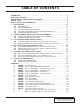
TABLE OF CONTENTS FOREWORD. . . . . . . . . . . . . . . . . . . . . . . . . . . . . . . . . . . . . . . . . . . . . . . . . . . . . . . . ii TABLE OF CONTENTS . . . . . . . . . . . . . . . . . . . . . . . . . . . . . . . . . . . . . . . . . . . . . . . iii CONGRATULATIONS ON YOUR PURCHASE . . . . . . . . . . . . . . . . . . . . . . . . . . . . . iv SAFETY FIRST . . . . . . . . . . . . . . . . . . . . . . . . . . . . . . . . . . . . . . . . . . . . . . . . . . . . . . v TOOL & SUPPLY REQUIREMENTS . . . . . .
ongratulations! You have purchased the finest street supercharger available for the Mustang GT. The centerpiece of this kit is the High-Efficiency PAXTON Supercharger, a mechanically driven centrifugal blower. This kit comes with all the parts you will need to install the supercharger. The instruction manual has been written in order of sequence, and photographs and drawings have been included to illustrate the text. This will allow you quick parts identification and orientation.
SAFETY FIRST Never rely solely on a floor jack when working underneath a vehicle. Always use jack stands that are rated for the weight of your vehicle, place them at the recommended lift points, and place your vehicle in “PARK” or “FIRST” gear with the parking brake set. Always use eye protection when using power tools, such as drills, saws, and grinders, or when working underneath a vehicle. Never smoke, use an open flame, or have spark producing items around gasoline or flammable objects.
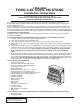
1996-2003 FORD 4.6L SOHC MUSTANG Installation Instructions 50 State Smog Legal, as per CARB EO #D-195-20 Congratulations on selecting the best performing and best backed automotive supercharger available today! Before beginning this installation, please read through this entire instruction booklet and the Street Supercharger System Owner's Manual which includes the Automotive Limited Warranties Program and the Warranty Registration form. Paxton supercharger systems are performance improving devices.
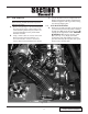
1.0 ECM REMOVAL C. Contact the Paxton Service Department for a Return Authorization Number. Send both the ECM and supplied credit tag to Paxton using the enclosed shipping box. *** NOTE *** Before removing the ECM, disconnect the positive cable from the battery. 1.1 A. Remove the passenger’s side front kick-panel from the interior of the vehicle. Remove the sound deadening material (if any) that is covering the ECM. Remove the plastic ECM hold-down bracket. B.
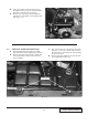
E. *** NOTE *** This manual covers model years 1996-2003. Some of the photographs and illustrations may be different but the removal and installation of components are similar. Once the assembly is out of the car, use a 10mm socket to remove the mass air flow sensor from the air filter housing. (See Fig. 1.1-d.) Place the mass air flow sensor aside to be re-installed in a later step. *** NOTE *** 2002-2003 models do not have a separate IAT sensor. (The IAT sensor is integrated with the factory MAF.) B.
G. Use a 7mm socket to remove the four coil pack bolts and move the coil pack toward the passenger’s side and out of your way. H. Remove the 13mm bolt, nut and stud bolt securing the coil bracket to the cylinder head. (See Fig. 1.1-f.) Fig. 1.1-f 1.2 COOLANT RESERVOIR REMOVAL A. Drain approximately one gallon of coolant from the radiator into an appropriate container. B. Remove the large hose from the coolant reservoir and drain the contents of the reservoir into a container. C.
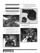
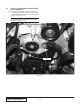
1.3 FACTORY TENSIONER AND RELATED PARTS REMOVAL A. Using a 13mm socket, remove the two nuts securing the tensioner limiting bracket. Set the bracket and hardware aside as they will not be reused. (See Fig. 1.3-a.) *** NOTE *** Some models and some model years may not have this bracket. (See Fig. 1.3-a.) REMOVE 13mm NUTS Fig. 1.3-a P/N: 4809655 ©2007 Paxton Automotive All Rights Reserved, Intl. Copr. Secured 16AUG07 v1.0 96-03MusGT(4809655v1.
F. B. Loosen (but do not remove) the four 10mm bolts on the water pump pulley. (See Fig. 1.3-b.) Use a 13mm socket to remove the idler pulley located above the belt tensioner. (See Fig. 1.3-d.) 13mm STUD BOLT REMOVE IDLER PULLEY Fig. 1.3-d Fig. 1.3-b G. Place the pulley aside to be reused in a later step. H. Remove three bolts at the front of the engine (passenger’s side), (see Fig. 1.3-e), a 10mm alternator mounting bolt (arrow “A”), and two 13mm timing cover bolts (arrows “B” and “C”). C.
I. 1.4 Using a 13mm socket, remove the two nuts and stud bolts located at the top of the passenger’s side cylinder head. (See Fig. 1.3-i.) FAN RESISTOR RELOCATION 2001-2003 Models Only A. Disconnect the wiring harness from the fan resistor. (See Fig. 1.4-a.) Remove the clips holding the fan resistor to the fan shroud. Attach the fan resistor to the supplied bracket using the supplied hardware. CONNECTOR MOUNT REMOVE Fig. 1.3-f J. Remove the electrical connector mount.
Fig. 1.4-c C. Re-attach the fan resistor to the wiring harness to ensure adequate wire length. (See Fig. 14-d.) Position the supplied fan bracket and hardware on the passenger’s side of the lower fan shroud. Mark two mounting points along the fan shroud and drill the holes. Attach the mounting bracket with the supplied hardware. Fig. 1.4-d 1-7 P/N: 4809655 ©2007 Paxton Automotive All Rights Reserved, Intl. Copr. Secured 16AUG07 v1.0 96-03MusGT(4809655v1.
This Page Left Intentionally Blank P/N: 4809655 ©2007 Paxton Automotive All Rights Reserved, Intl. Copr. Secured 16AUG07 v1.0 96-03MusGT(4809655v1.
2.0 SUPERCHARGER MOUNTING BRACKET ASSEMBLY *** NOTE *** See Appendix for the model year’s supercharger bracket assembly procedure. A. Install the supercharger idler pulley bracket using the supplied hardware. Install the provided spacer between bracket and alternator. (See Fig. 2.0-a.) This operation will be performed on all model years. *** NOTE *** This photo is for illustration purposes. It will be easier for you to install this bolt/spacer first, then install the other two mounting bolts. (See Fig. 2.
D. Before installing the main supercharger bracket, the A/C refrigerant refilling port must be bent from its upright position downward so that the cap is facing the driver’s side fender. (See Fig. 2.0-f.) Note that this operation will be performed on all model years except model year 2000. This hose assembly will be replaced with the provided A/C hose assembly. *** NOTE *** 1996-1998 Models Only - The A/C line bracket should be placed between the spacer and the cylinder head. (See Fig. 2.0-l.
G. Reinstall the water pump pulley removed in an earlier step. (See Fig. 2.0-j.) Fig. 2.0-l Completed Supercharger Mounting Bracket Fig. 2.0-j Route the supercharger and accessory drive belt. *** NOTE *** On 2000-2003 models the drive belt needs to be routed before the rear S/C mounting plate is installed. Fig. 2.0-k Fig. 2.0-m *** NOTE *** The belt must be routed BEFORE this bolt and spacer are installed. 2-3 P/N: 4809655 ©2007 Paxton Automotive All Rights Reserved, Intl. Copr. Secured 16AUG07 v1.
2.1 SUPERCHARGER INSTALLATION A. Install the supercharger oil return line (see assembly 1019328) to the supercharger drain fitting and secure with the hose clamp provided.. (See Fig. 2.1-a.) *** NOTE *** The hose clamp screw head should be parallel to the supercharger mounting base. OIL FEED FITTING Fig. 2.1-b H. Install the spacer and coil mounting bracket after installing the supercharger. Fig 2.1-a B. Locate the 1/8" x -4 x 90° oil feed fitting. (See assembly 1019327.
3.0 SUPERCHARGER OIL FEED AND DRAIN (1996-2003 Models) E. Install the line, and tighten moderately - no sealant is required. (See Fig. 3.0-b.) A. Your Paxton Automotive NOVI supercharger uses pressurized engine oil for lubrication. Use an oil sending unit socket (Snap-On tools; part number 6152 or equivalent) to remove the oil sending unit on the underside of the oil filter housing. (See Fig. 3.0-a.) Fig. 3.0-b 3.1 SUPERCHARGER OIL DRAIN INSTALLATION (1996-2003 Models) A.
D. Next, apply a small amount of anti-seize lubricant to the tip of the punch, and insert it into the pilot hole. Using the appropriate tool, (an air hammer works the best), use small bursts until the punch is inserted up to its shoulder. The finished hole size should be 9/16". (See Fig. 3.1-b.) G. Install the supplied drain-back hose fitting so that the elbow is oriented toward the passenger’s side, away from the harmonic balancer/ crank pulley.
4.0 FUEL INJECTOR REPLACEMENT 19992003 Models Only A. B. C. D. E. F. B. Install the supplied length of rubber hose to the end of the hard crank case ventilation line that runs from the driver’s side valve cover across the engine, (See Fig. 4.1-b.) Disconnect the eight fuel injector wiring clips and retainers from the fuel injectors. Release any residual fuel pressure from the rail by opening the schrader valve on the rail.
4.2 AIR INLET INSTALLATION FACTORY AIR TEMPERATURE SENSOR (NOT ON 2002+ MODELS) *** NOTE *** The MAF mounting bracket you receive may be different than what is shown but the assembly is the same. 3-1/2" ELBOW A. Assemble the MAF, mounting bracket, MAF/air filter adapter and air filter. (See Fig. 4.2-a & Appendix “G”.) B. Using the supplied 1/4-20 hardware, mount the MAF meter to the MAF bracket and secure. (See Fig. 4.2-a.
C. D. Attach the supplied K & N air filter, 3-1/2" sleeve, 90° x 3-1/2" elbow and #56 hose clamps to the MAF and secure. G. *** NOTE *** 1996-2001 models use the 90° x 3-1/2" plastic inlet elbow with the hole and grommet in the side. 2002+ models use the 90° x 3-1/2" plastic elbow without a hole in the side. Both elbows have been supplied. H. Route the factory temperature sensor and MAF sensor connectors out through the inner fender opening. Reattach the connectors to the relocated sensors.
Fig. 4.2-e J. Remove the 2" bolts securing the lower reservoir bracket. Reinstall the support bracket using one of the existing holes and factory fasteners and the self-tapping screw provided. K. Re-install the stock coolant reservoir. (See Fig. 4.2-f.) *** NOTE *** The Novi 2000 application will have spacers provided to move the coolant reservoir to gain clearance for the supercharger. COOLANT RESERVOIR RELOCATION BRACKETS Fig. 4.2-f P/N: 4809655 ©2007 Paxton Automotive All Rights Reserved, Intl.
5.0 FORD 4.6L IN-TANK FUEL PUMP INSTALLATION (1999-2003 Models) A. Raise the rear of the car and support it with jack stands. B. Open the fuel door and remove the fuel cap and the three filler neck screws using a 10mm socket. C. Remove the fuel filter inlet line with a 3/8" spring-lock tool. D. With the weight of the fuel tank supported with a jack, remove the bolts securing the two fuel tank straps. E.
This Page Left Intentionally Blank P/N: 4809655 ©2007 Paxton Automotive All Rights Reserved, Intl. Copr. Secured 16AUG07 v1.0 96-03MusGT(4809655v1.
Position the fuel management unit (FMU) against the inner fender ahead of the right side shock tower about an inch from the top. Mark and drill two holes in the inner fender to mount the FMU. Secure with the sheet metal screws provided. (See Figs. 5.1-a, 5.1-b, 5.1-c.) FUEL MANAGEMENT UNIT (FMU) VACUUM LINE INLET OUTLET FACTORY SPRINGLOCK CONNECTOR FACTORY QUICKDISCONNECT FITTING FACTORY REGULATOR FUEL FEED LINE A. FUEL MANAGEMENT/UNIT (1996-1998 Models Only) FUEL RETURN LINE 5.
B. C. D. E. F. Disconnect and discard the factory rubber fuel return line running from the fuel rail (the return line DOES NOT have a pressure test fitting on it) to the steel return line (the smaller of the two) located behind the right side shock tower using a spring lock disconnect tool. Connect the FMU inlet hose (the hose that goes to the 90° fitting on the side of the FMU) to the return side of the factory fuel regulator on the fuel rail.
5.2 FORD 4.6L FUEL PUMP INSTALLATION (1996-1998 Models Only) B. Connect the power wire from the relay (Terminal #30) to the battery positive (+) terminal. (See Fig. 5.2-d.) POWER FROM RELAY TO TERMINAL Fig. 5.2-d C. Locate the wiring harness connection from the battery. Connect the gray trigger wire from the relay (Terminal #86) with the supplied quick connector to the solid red wire coming from the wiring harness connection. (See Fig. 5.2-e.) QUICK CONNECTOR POWER WIRE TO TRIGGER RELAY Fig. 5.2-e D.
E. Disconnect the factory fuel line at the fuel filter using the supplied tool. Connect the male fitting from the fuel pump to the line that you removed from the fuel filter. Connect the female end from the fuel pump to the fuel filter. F. The in-line auxiliary fuel pump is installed next. Remove the spare tire from the well in the trunk. Mount the pump/bracket assembly by drilling two 1/4" holes in the spare tire well using the bracket as a template. 1.
6.0 CHECK-OUT PROCEDURES We know that you are anxious to get out and drive your new vehicle, but please take a little bit more time to perform these simple check-out steps. A. Inspect all wiring harnesses and electrical connections. Make sure that all items are properly routed, connected and secured. B. Check all hoses, lines, and fittings for properly secured connections. C. Make certain all fasteners, brackets, and clamps are installed and properly tightened. D.
6.1 COMPLETED INSTALLATION Fig. 6.1-a P/N: 4809655 ©2007 Paxton Automotive All Rights Reserved, Intl. Copr. Secured 16AUG07 v1.0 96-03MusGT(4809655v1.
APPENDIX Please realize that PAXTON Automotive is constantly improving the performance and look of the NOVI 1000/2000 superchargers. Parts in your kit may appear differently than what is pictured in this manual. This is due to photographs taken in preproduction, a change in material costs, or an improvement in performance. Rest assured that you have purchased the best quality kit that PAXTON Automotive manufactures at this time. The installation of the components will remain the same.
P/N: 4809655 ©2007 Paxton Automotive All Rights Reserved, Intl. Copr. Secured 16AUG07 v1.0 96-03MusGT(4809655v1.0) A-2 ITEM NO. 1 2 3 4 5 6 7 8 9 10 11 12 13 QTY. 1 1 1 1 1 1 1 1 1 8 1 1 20 A FINISH WEIGHT APPR. Kit, Parts List NONE 0.0 LBS G. COMPTON SCALE: 12/11/00 SIZE UNLESS OTHERWISE SPECIFIED CAD GENERATED DRAWING, DIMENSIONS ARE IN INCHES DO NOT MANUALLY UPDATE TOLERANCES ARE: .XX± .01 DECIMALS: .XXX±.005 DATE APPROVALS ±1/2• FRACTIONS: DRAWN A.
A-3 P/N: 4809655 ©2007 Paxton Automotive All Rights Reserved, Intl. Copr. Secured 16AUG07 v1.0 96-03MusGT(4809655v1.0) 2 2 13 11 4. HEAT TO 200°F TO EASE ASSEMBLY. 3. TORQUE TO 36 FT-LBS. 2. SHIM IMPELLER TO .017 WORKING HEIGHT USING ITEMS 26, 27, 28, 29, 30, 31 AND 32 (FLOOR STOCK) AS REQUIRED. 1. ALL PARTS TO BE SUITABLY PROTECTED AT ALL TIMES TO PREVENT DAMAGE.
P/N: 4809655 ©2007 Paxton Automotive All Rights Reserved, Intl. Copr. Secured 16AUG07 v1.0 96-03MusGT(4809655v1.0) A-4 13 4 20 35 36 TO EXHAUST MANIFOLD 21 22 33 4 1 TO VACUUM SOURCE 32 TO ENGINE TO SMOG PUMP 31 EXISTING STOCK SCREW 26 INE ENG TO 13 19 2 5 23 16 15 16 25 SEE NOTE 2 17 16 TO ENGINE OR 5 13 6 25 16 C 1. PARTS TO BE SHIPPED LOOSE. 2. IMPORTANT: CUT ITEM 17 SO THAT IT DOES NOT PROTRUDE PAST MACHINED SURFACE OF ITEM 3. DO NOT USE A 1-1/2" BOLT. 3.
A-5 P/N: 4809655 ©2007 Paxton Automotive All Rights Reserved, Intl. Copr. Secured 16AUG07 v1.0 96-03MusGT(4809655v1.0) 11 20 4 21 1. SHIP THIS ITEM LOOSE. TO S/C TO ENGINE NOTES: UNLESS OTHERWISE SPECIFIED 22 TO ENGINE 2 5 23 TO S/C 6 7 2 2 1 3 2 3 TO S/C 11 26 D 6 3 1016609 24 6 8 2 26 13 13 27 28 25 REPLACE STOCK BOLT ON WATER PUMP 29 17 ? 13 16 19 18 9 1 15 FINISH WEIGHT ASY, S/C MTG BRKT NONE APPR. 7.
P/N: 4809655 ©2007 Paxton Automotive All Rights Reserved, Intl. Copr. Secured 16AUG07 v1.0 96-03MusGT(4809655v1.0) A-6 16 20 27 15 16 8 14 10 29 TO ENGINE TO S/C TO S/C NOTES: UNLESS OTHERWISE SPECIFIED 1. SHIP THIS ITEM LOOSE. TO ENGINE 8 8 18 TO S/C 8 19 1 E 8 3 18 8 1016616 2 20 14 18 26 8 21 13 16 14 16 22 16 REPLACE STOCK BOLT ON WATER PUMP 26 7 6 1 ITEM NO. QTY.
A-7 P/N: 4809655 ©2007 Paxton Automotive All Rights Reserved, Intl. Copr. Secured 16AUG07 v1.0 96-03MusGT(4809655v1.0) 22 18 TO ENGINE 17 2 1. THESE ITEMS SHIP LOOSE. NOTES: UNLESS OTHERWISE SPECIFIED: 28 TO ENGINE 4 TO S/C 3 REPLACE STOCK STUD ON TIMING COVER UPPER PASSENGER (R.H.
P/N: 4809655 ©2007 Paxton Automotive All Rights Reserved, Intl. Copr. Secured 16AUG07 v1.0 96-03MusGT(4809655v1.0) A-8 NOTES: UNLESS OTHERWISE SPECIFIED 1. USED IN KITS 1001814-1 AND 1001819 ONLY. 2 4 3 4 6 8 12 16 5 18 10 11 4x 4x 13 14 13 6 1 19 FINISH WEIGHT ASY, AIR INTAKE NONE APPR. 10.3 LBS G. COMPTON SCALE: 10/30/00 SIZE D 1:2 1015933 DO NOT SCALE DRAWING DWG. NO. ASY, AIR INTAKE 1996-2003, MUSTANG REV.
A-9 P/N: 4809655 ©2007 Paxton Automotive All Rights Reserved, Intl. Copr. Secured 16AUG07 v1.0 96-03MusGT(4809655v1.0) NIPPLE ON P/N 4810127-6 TO COMPRESSOR BYPASS 3 2 3x 4 6x H 1 1017017 TO S/C OUTLET 1017017-P ASY NUMBER 1017017 6 ITEM 3 1 3 1 QT 1 1 1 1 PART NUMBER 4PFH012-041 4PFH012-020 4PFH012-048 4PFH012-028 5 FINISH WEIGHT ASY, AIR DISCHARGE NONE APPR. ----- LBS G. COMPTON D SCALE: 1:1.
P/N: 4809655 ©2007 Paxton Automotive All Rights Reserved, Intl. Copr. Secured 16AUG07 v1.0 96-03MusGT(4809655v1.0) A-10 I 1019336 1 2 7P125-004 7P250-082 1 1 1 1 2 3 4 FINISH WEIGHT ASY, OIL SUPPLY NONE APPR. 0.2 LBS ----- ----- SCALE: SIZE 3:4 C DO NOT SCALE DRAWING 1019336 ASY, S/C OIL SUPPLY DWG. NO. REV.
A-11 P/N: 4809655 ©2007 Paxton Automotive All Rights Reserved, Intl. Copr. Secured 16AUG07 v1.0 96-03MusGT(4809655v1.0) 1. SHIP THIS ITEM LOOSE. NOTES: UNLESS OTHERWISE SPECIFIED TO OIL PAN 4 (FRONT OF OIL PAN) LOCATION FOR ITEM 5 1.75 3 2 PUNCH HOLE WITH ITEM 6 1.00 J OIL PAN 5 1019328 QTY. 1.083' 1 1 1 2 1 FINISH WEIGHT ASY, OIL RETURN NONE APPR. 0.8 LBS ----- ----- SCALE: SIZE PART NO.
P/N: 4809655 ©2007 Paxton Automotive All Rights Reserved, Intl. Copr. Secured 16AUG07 v1.0 96-03MusGT(4809655v1.0) A-12 5 -01 4 TO AIR INTAKE ASY 4 4 5 K 4 -02 TO AIR DISCHARGE ASY 1 1015506 3.25" ±.06 5 5 D ITEM NO. 1 4 10 11 12 13 NONE WEIGHT APPR. ASY, COMPRESSOR BYPASS FINISH 2.8 LBS ----- 5 ----- 13 2.50" ±.06 SCALE: 3:4 D 1996-2003, MUSTANG DWG. NO. 1015506 DO NOT SCALE DRAWING REV.
A-13 P/N: 4809655 ©2007 Paxton Automotive All Rights Reserved, Intl. Copr. Secured 16AUG07 v1.0 96-03MusGT(4809655v1.0) TO RADIATOR 2 3 2 2 L 1 1015309 MODIFIED 1 3 1 1 2 3 NONE WEIGHT APPR. --------- LBS ASY, RADIATOR HOSE MODIFICATION FINISH ----- D 1996-2003, MUSTANG DWG. NO. 1015309 DO NOT SCALE DRAWING REV.
P/N: 4809655 ©2007 Paxton Automotive All Rights Reserved, Intl. Copr. Secured 16AUG07 v1.0 96-03MusGT(4809655v1.0) A-14 TO GAS TANK 1. TO BE SHIPPED LOOSE NOTES: UNLESS OTHERWISE SPECIFIED TO FUEL RAIL 4 M 1017700 3 2 ITEM NO. 2 3 4 6 7 1 8 9 10 1 11 11 QTY. 2 1 1 2 1 1 1 1 1 10 ASY, FUEL CONTROL D 1017700 DO NOT SCALE DRAWING DWG. NO.: KIT, FUEL CONTROL '96-'98 MUSTANG REV.
A-15 CHASSIS GND 26 7 1. SHIP THIS ITEM LOOSE 12 BLACK 14 Ga WIRE 8" LG NOTES: UNLESS OTHERWISE SPECIFIED 16 3 1 FACTORY FUEL FITTING FACTORY FUEL FILTER 3 2 11 TRIGGER FROM TERM. #86 4 10 ENG 21 TO INE 22 17 23 N 24 TO BATTERY POS. (+) FROM TERM. #30 FACTORY FUEL LINE 86 85 30 12 25 14 11 9 18 20 4x TO INSIDE OF FENDERWELL 3 6 5 1 ITEM 1 2 3 4 5 6 7 8 9 10 11 12 13 14 15 16 17 18 19 20 21 22 23 24 25 26 27 28 QTY 1 1 3 1 1 .16' 1' 1.75' 2 2 4 1 1 1 1 .67' .
P/N: 4809655 ©2007 Paxton Automotive All Rights Reserved, Intl. Copr. Secured 16AUG07 v1.0 96-03MusGT(4809655v1.0) A-16 1. ALL ITEMS SHIPPED LOOSE. NOTE: UNLESS OTHERWISE SPECIFIED- O ITEM NO. 1 1017734 QTY. 1 DESCRIPTION FUEL PUMP, 255 LPH NONE WEIGHT APPR. ASY, FUEL PUMP / IN-TANK FINISH 2.0 LBS ----- ----- UNLESS OTHERWISE SPECIFIED CAD GENERATED DRAWING, DIMENSIONS ARE IN INCHES DO NOT MANUALLY UPDATE TOLERANCES ARE: .XX± .01 DECIMALS: .XXX±.005 DATE APPROVALS ±1/2• FRACTIONS: DRAWN G.
A-17 P/N: 4809655 ©2007 Paxton Automotive All Rights Reserved, Intl. Copr. Secured 16AUG07 v1.0 96-03MusGT(4809655v1.0) A/C SUPERCHARGER P WATER PUMP BELT ROUTING DIAGRAM B 1:1 2000-2003 DO NOT SCALE DRAWING DWG. NO.: BELT ROUTING DIAGRAM '00 -'03 MUSTANG REV. NC SHEET 1 OF 1 1300 BEACON PLACE OXNARD, CA 93033 TEL: (805) 604-1336 FAX: (805) 604-1337 POWER/STEERING UNLESS OTHERWISE SPECIFIED CAD GENERATED DRAWING, DIMENSIONS ARE IN INCHES DO NOT MANUALLY UPDATE TOLERANCES ARE: .XX± .
P/N: 4809655 ©2007 Paxton Automotive All Rights Reserved, Intl. Copr. Secured 16AUG07 v1.0 96-03MusGT(4809655v1.0) A-18 NOTE: 1. APPLICABLE STANDARD/SPECIFICATIONS ANSI Y14-5-1982, DIMENSIONS AND TOLERANCES 2. REMOVE ALL BURRS AND SHARP EDGES A/C COMPRESSOR PULLEY FACTORY IDLER PULLEY Q BELT ROUTING DIAGRAM 1996-1999 DO NOT SCALE DRAWING DWG. NO.: BELT ROUTING DIAGRAM 96-99 MUSTANG REV.
This Page Left Intentionally Blank A-19 P/N: 4809655 ©2007 Paxton Automotive All Rights Reserved, Intl. Copr. Secured 16AUG07 v1.0 96-03MusGT(4809655v1.
Paxton Automotive • 1300 Beacon Place . Oxnard CA 93033 805 604-1336 • FAX (805) 604-1337 DP/N: 4809655 - v1.