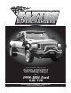
SUPERCHARGERS Owners Installation Manual for the PAXTON AUTOMOTIVE NOVI 2000 Supercharger for 1998-2001 Ford 6.8L V10 PAXTON AUTOMOTIVE 1300 BEACON PL. OXNARD CA 93033 (805) 604-1336 • FAX (805) 604-1337 P/N 4809606 v4.
FOREWORD T his manual provides information on the installation, maintenance and service of the Paxton supercharger kit expressly designed for the 1998-2001 Ford 6.8L V-10 F-250, F-350/Excursion. Contact Paxton Automotive Corporation for any additional information regarding this kit and any of these modifications at (805) 604-1336 8:00 a.m. - 4:30 p.m. P.S.T.
TABLE OF CONTENTS FOREWORD . . . . . . . . . . . . . . . . . . . . . . . . . . . . . . . . . . . . . . . . . . . . . . . . . . . . . . . . . . . . . .ii TABLE OF CONTENTS . . . . . . . . . . . . . . . . . . . . . . . . . . . . . . . . . . . . . . . . . . . . . . . . . . . . .iii IMPORTANT NOTES . . . . . . . . . . . . . . . . . . . . . . . . . . . . . . . . . . . . . . . . . . . . . . . . . . . . . .iv INTRODUCTION . . . . . . . . . . . . . . . . . . . . . . . . . . . . . . . . . . . . . . . . . . . . . . .
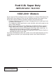
Ford 6.8L Super Duty IMPORTANT NOTES 1998-2001 Models This kit requires ECM modification and the installation of a Paxton ECM Module. The ECM must be sent directly to Paxton by the installing customer (the charge for this service with module installation has been included in the purchase price). • Included in this kit is a prepaid next-day air shipping box and a credit tag for one (1) Paxton ECM Module.
INTRODUCTION C ongratulations! You have purchased the finest street supercharger available for the Ford V10. The centerpiece of this kit is the High Efficiency NOVI 2000 Supercharger, a mechanically driven centrifugal supercharger. This kit comes with all of the parts you will need to install the supercharger. This instruction manual has been grouped in order of sequence, with photographs and drawings to illustrate the text. This will allow you quick part identification and orientation.
You are undoubtedly eager to get started with your project, but take a little more time to insure that your safety is not in jeopardy. A moment’s lack of attention can result in an accident, as can failure to observe some simple safety precautions. The possibility of an accident always exists, and the following points should not be considered a comprehensive list of all of the dangers.
1998-2001 FORD SUPER DUTY Installation Instructions 1998-2001 50 State Smog Legal, as per CARB EO #P-195-19 Congratulations on selecting the best performing and best backed automotive supercharger available today... the NOVI 2000 Supercharger! Before beginning this installation, please read through this entire instruction booklet and the Street Supercharger System Owner's Manual which includes the Automotive Limited Warranties Program and the Warranty Registration form.
We look forward to hearing from you, particularly if you have any comments or suggestions regarding this manual. TRANSMISSION WARNING/DISCLAIMER: Due to the increased horsepower and torque generated by the Paxton Novi 2000 supercharger, your transmission may require modification to prevent premature wear or damage—especially if plan to use your vehicle in high demand situations, such as towing.
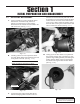
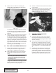
Section 1 INITIAL PREPARATION AND DISASSEMBLY 1.1 AIR INTAKE DISASSEMBLY tion between the throttle body and front air filter enclosure. You will need to unplug the Mass Airflow Sensor connector on the inner fenderwell. Using a 10mm socket and ratchet, remove the three bolts securing the air filter bracket and remove it from the vehicle. (See Fig. 1.1-c.) A. Using a screwdriver, remove the black rubber tube between the throttle body and the air cleaner by loosening the two hose clamps.
E. C. Remove the fasteners that secure the fan shroud to the radiator. D. After you remove the fan from the water pump, lift the fan and fan shroud together from the engine compartment and set it aside to be reinstalled at a later step. (See Fig. 1.2-a.) Remove the two 10mm nuts retaining the MASS AIR FLOW METER and separate the two pieces. (See Fig. 1.1-e.) Fig. 1.1-e F. 1.2 The MASS AIR FLOW METER will be used in a later step.
1.4 WIRE ROUTING AND MODIFICATIONS A. On the front of the engine, (driver’s side), you will find two large black electrical connectors attached to a bracket. (See Fig. 1.4-a.) CUT HERE DISCARD THIS SECTION Fig. 1.4-c D. Discard the part with the two holes in it and retain the section that the electrical connectors clip to. The two connectors and wiring harness, will now be routed directly in front of the two steel brake lines. E.
F. Reclip the two large connectors back onto the modified stock bracket (from Step E). Attach the bracket and connectors with the two supplied wire ties to the heavy-duty plastic wire loom as shown. (See Fig. 1.4-e.) Fig. 1.4-e G. Located on the driver’s side, in front of the cylinder head is the cam sensor. Extend the two wires coming from the cam sensor along with the shielded white wire that runs parallel with the cam sensor wires, using the supplied three wires and six Butt connectors. (See Fig. 1.
Section 2 SUPERCHARGER ASSEMBLY INSTALLATION 2.1 OIL DRAIN LINE INSTALLATION E. A. Locate the supplied oil drain assembly #1019344. Mark the front of the oil pan 1 inch below the pan rail and between the two pan rail bolts, directly in the center of the small “hump (see Appendix J). B. Drill a pilot hole with a 3/16" drill bit. Smear the drill bit with heavy grease first to prevent small metal particles from falling into the pan. C.
2.2 OIL FEED ASSEMBLY INSTALLATION 2.3 CRANK PULLEY ASSEMBLY INSTALLATION A. Locate the supercharger crank pulley Assembly 1015611 that is provided. B. Bolt the Paxton Supercharger crank pulley to the face of the stock crank pulley, using the (3)supplied allen-head bolts. (See Fig. 2.3-a.) A. Locate the supplied oil feed line in the Assy 1019350. On the passenger-side cylinder head, there is a small pipe plug, near the front and below the oil fill neck. B.
2.4 S/C MOUNTING PLATE ASSEMBLY INSTALLATION 2.5 A. Slide the three black aluminum spacers, about 1/2" thick, over the three studs protruding from the front of the driver’s side head. B. Slide the supercharger mounting bracket over the studs and spacers and attach with the supplied three nuts and one bolt.(Appendix “C”.) Hand tighten only at this time. C. Slide the mounting block between the supercharger side-brace and the cylinder head.
This Page Left Intentionally Blank P/N: 4809606 ©2005 Paxton Automotive All Rights Reserved, Intl. Copr. Secured 06SEP05 v4.0 FordV10(4809606v4.
Section 3 DISCHARGE DUCT ASSEMBLY INSTALLATION 3.1 DISCHARGE DUCT ASSEMBLY INSTALLATION A. Locate discharge Assembly 1016011. B. Install the supplied 3.0" x 2.0"L sleeve to the discharge duct by pushing the sleeve all the way onto the discharge tube. C. Attach the 4.25" x 2.0"L sleeve to the throttle body with the clamps provided. D. Position the discharge tube between the throttle body and the supercharger. Slide both sleeves into position and secure with the supplied hose clamps.(See Fig 3.1-a.
This Page Left Intentionally Blank P/N: 4809606 ©2005 Paxton Automotive All Rights Reserved, Intl. Copr. Secured 06SEP05 v4.0 FordV10(4809606v4.
Section 4 SUPERCHARGER AIR INLET TUBE 4.1 SUPERCHARGER INLET DUCT ance. Attach the flex hose to the aluminum elbow. Next, connect the factory PCV hose into the hose coming from the intake elbow. (See Fig. 4.1-a.) A. Locate the supplied inlet duct Assembly 1015911 in the kit. Plug the air temp sensor, previously removed in an earlier step, into the open hole on the rubber elbow. (See Fig. 4.1-a.) 4.2 *** NOTE *** Model year 2000 - engines will not have this sensor.
This Page Left Intentionally Blank P/N: 4809606 ©2005 Paxton Automotive All Rights Reserved, Intl. Copr. Secured 06SEP05 v4.0 FordV10(4809606v4.
Section 5 REINSTALLING FAN AND SHROUD 5.1 REINSTALLING FAN & SHROUD C. A. Install the supplied fan spacer to the factory fan clutch. (See Fig. 5.1-a.) Re-install the fan shroud, re-attach the coolant reservoir. Re-install the upper radiator hose to the radiator and the end marked “R” to the thermostat housing (reversing the hose). This is done to clear the supercharger bracket. Fill radiator reservoir per the manufacturer’s specification. (See Fig. 5.1-b.) Fig 5.1-a B.
This Page Left Intentionally Blank P/N: 4809606 ©2005 Paxton Automotive All Rights Reserved, Intl. Copr. Secured 06SEP05 v4.0 FordV10(4809606v4.
Section 6 FUEL PUMP INSTALLATION 6.1 FUEL PUMP INSTALLATION 6.3 *** NOTE *** Depressurize the fuel system by removing the cap on the schraeder valve and depressing the valve using a pen or small screwdriver to release fuel pressure. Cover the valve with a rag while this is being done to prevent fuel spray. FUEL CONTROL UNIT INSTALLATION A. Locate the fuel return line quick connect in the frame rail on the driver’s side. Disconnect the line and install the fuel control unit as per Appendix “H”.
This Page Left Intentionally Blank P/N: 4809606 ©2005 Paxton Automotive All Rights Reserved, Intl. Copr. Secured 06SEP05 v4.0 FordV10(4809606v4.
Section 7 CHECK-OUT PROCEDURES 7.1 CHECK-OUT PROCEDURES cle is now different than what you are used to. Please drive cautiously until you have grown accustomed to the feel of your vehicle. C. Please see the service manual included in your kit for information on the service and maintenance of your PAXTON Supercharger. Belt tightening, troubleshooting, special tuning requirements, and warranty information is also included in the Service Manual. A.
This Page Left Intentionally Blank P/N: 4809606 ©2005 Paxton Automotive All Rights Reserved, Intl. Copr. Secured 06SEP05 v4.0 FordV10(4809606v4.
APPENDIX Please understand that Paxton Automotive is constantly improving the NOVI supercharger system. As a result, some of the parts in your kit may not look exactly like the parts pictured in this manual. This may be due to pictures taken in pre-production, a change in materials, or even in a change in the design in the vehicle from one model year to the next. Rest assured that your supercharger kit is the most up-to-date kit that Paxton produces for your vehicle at this time.
P/N: 4809606 ©2005 Paxton Automotive All Rights Reserved, Intl. Copr. Secured 06SEP05 v4.0 FordV10(4809606v4.0) A-2 12 13 11 14 34 LONG HUB AWAY FROM S/C 8 9 6 ? 4 4 REQD 19 3 2 2 Appendix B 1 32 31 30 26 AS REQD 29 28 27 AS REQD 3 16 1016111 33 3 2 32 2 4 20 NONE WEIGHT ----21:8 LBS ASY, NOVI 2000 SUPERCHARGER FINISH APPR. ----- SCALE: SIZE S/C ROTATION 1998-2001 6.8L FORD F-350 REV.
A-3 P/N: 4809606 ©2005 Paxton Automotive All Rights Reserved, Intl. Copr. Secured 06SEP05 v4.0 FordV10(4809606v4.0) 15 14 16 17 15 14 9 18 19 6 TO S/C 13 17 12 10 9 10 1016311 TO TIMING CHAIN COVER Appendix C 10 11 10 11 8 8 TO ENGINE STUD TO ENGINE 3 2 7 ITEM NO. QTY. 1 1 2 2 3 2 4 1 5 1 6 2 7 1 8 3 9 3 10 4 11 3 12 1 13 1 14 2 15 2 16 1 17 2 18 6 19 6 20 1 PART NO.
P/N: 4809606 ©2005 Paxton Automotive All Rights Reserved, Intl. Copr. Secured 06SEP05 v4.0 FordV10(4809606v4.0) A-4 3 2 1 Appendix D STOCK HARMONIC BALANCER 1 4 3 2 3 1 1 3 QTY ITEM I PU DLE LL EY 2A048-740 7J010-002 7C010-038 4PFM018-011 PART NUMBER 1015611 FINISH APPR. WEIGHT ASY, CRANK PULLEY NONE ?.? LBS ----- ----- UNLESS OTHERWISE SPECIFIED CAD GENERATED DRAWING, DIMENSIONS ARE IN INCHES DO NOT MANUALLY UPDATE TOLERANCES ARE: .XX± .01 DECIMALS: .XXX±.
A-5 P/N: 4809606 ©2005 Paxton Automotive All Rights Reserved, Intl. Copr. Secured 06SEP05 v4.0 FordV10(4809606v4.0) 5 4 3 2 Appendix E 1 1 1 1 4 5 6 1 1 3 8 2 2 1 1 1 7 QTY ITEM PART NO. 7C080-035 4PGM017-011 1210515 7A375-276 7J375-044 4PGM011-061 7A375-077 4PFT011-032 1016911 FINISH WEIGHT ASY, BELT TENSIONER NONE APPR. ----- LBS ----- ----- UNLESS OTHERWISE SPECIFIED CAD GENERATED DRAWING, DIMENSIONS ARE IN INCHES DO NOT MANUALLY UPDATE TOLERANCES ARE: .XX± .
P/N: 4809606 ©2005 Paxton Automotive All Rights Reserved, Intl. Copr. Secured 06SEP05 v4.0 FordV10(4809606v4.0) A-6 NOTES: (UNLESS OTHERWISE SPECIFIED) 1. ITEM 17 IS REPLACEMENT FOR STOCK PCV VALVE. 10 9 12 11 13 14 1 15 1 Appendix F 16 18 3 4 5 6 7 ITEM 1 2 3 4 5 6 7 8 9 10 11 12 13 14 15 16 17 18 QTY 1 1 1 4 4 2 1 1 2 1' 1 2 1 1 .38' 1 1 1 6 1015911 FINISH WEIGHT ASY, AIR INTAKE NONE APPR.
A-7 P/N: 4809606 ©2005 Paxton Automotive All Rights Reserved, Intl. Copr. Secured 06SEP05 v4.0 FordV10(4809606v4.0) 1 2 1 4 Appendix G 3 6 5 HOSE, TURBO 3.00"I.D. x 2" LG BLK 7PS300-200 1 2 1 4 5 6 FINISH WEIGHT ASY, AIR DISCHARGE NONE APPR. - - - - - LBS ----- ----- SCALE: ?:? B CLAMP, HOSE #48 4PFT012-020 7R002-048 1 3 SIZE CLAMP, HOSE #12 7R002-012 1 2 1016011 DO NOT SCALE DRAWING DWG. NO. ASY, AIR DISCHARGE 1998-2001 FORD 6.8L V10 REV.
P/N: 4809606 ©2005 Paxton Automotive All Rights Reserved, Intl. Copr. Secured 06SEP05 v4.0 FordV10(4809606v4.0) A-8 2 1 1. P/N 1010711 HOSE LENGTH IS LEFT LONG INTENTIONALLY. CUSTOMER WILL ROUTE AND CUT HOSE TO SUITABLE LENGTH. 3 VEHICLE FRAME RAIL 3 Appendix H 1017711 5 6 SEE NOTE 1 SEE NOTE 1 5 6 9 TO GAS TANK ITEM 1 2 3 4 5 6 7 8 9 10 11 QTY 1 2 4 2 2 2 1 1 1 8' 1 NONE WEIGHT APPR. ASY, FUEL CONTROL UNIT FINISH ----- LBS ----- ----- D 1017711 DO NOT SCALE DRAWING DWG. NO.
A-9 P/N: 4809606 ©2005 Paxton Automotive All Rights Reserved, Intl. Copr. Secured 06SEP05 v4.0 FordV10(4809606v4.0) 12 APPROX. 20" LONG 11 1 12 7 2 1 10 8 18 4 7 2 22 24 17 4 PLACES 16 5 6 Appendix I 12 1017721 TO FUSE BOX BATTERY POS(+) (TERM. #30) TO SWITCHED 12V SOURCE (FUEL PUMP RELAY TRIGGER) (TERM. #86) 6 3 NOTES: UNLESS OTHERWISE SPECIFIED 1. ITEM 11, HOSE LENGTH IS LEFT LONG INTENTIONALLY. CUSTOMER WILL ROUTE AND CUT HOSE TO SUITABLE LENGTH. 2.
P/N: 4809606 ©2005 Paxton Automotive All Rights Reserved, Intl. Copr. Secured 06SEP05 v4.0 FordV10(4809606v4.0) A-10 NOTES: UNLESS OTHERWISE SPECIFIED 1. SHIP THIS ITEM LOOSE. (FRONT OF OIL PAN) LOCATION FOR ITEM 2 1.75 2 OIL PAN 3 Appendix J TO OIL PAN PUNCH HOLE WITH ITEM 4 1.00 10179344 QTY. 2.46' 1 2 1 NONE WEIGHT APPR. 0.8 LBS ----- ASY, SLUPERCHARGER OIL RETURN FINISH ----- 3:4 C 1019344 DO NOT SCALE DRAWING DWG. NO. ASY, OIL RETURN 1998-2001 FORD 6.8L V-10 REV.
A-11 P/N: 4809606 ©2005 Paxton Automotive All Rights Reserved, Intl. Copr. Secured 06SEP05 v4.0 FordV10(4809606v4.0) Appendix K 101793450 1 2 2 7P125-004 PART NO. 7U250-000-465 TO CYLINDER HEAD NONE WEIGHT APPR. 0.2 LBS ----- ASY, SLUPERCHARGER OIL FEED FINISH ----- SCALE: SIZE 3:4 C DO NOT SCALE DRAWING 1019350 ASY, S/C OIL SUPPLY DWG. NO. REV. NC SHEET 1 OF 1 1300 BEACON PLACE OXNARD, CA 93033 TEL: (805) 604-1336 FAX: (805) 604-1337 TO S/C ASY 1998-2001 FORD 6.
S U P E R C H A R G E R S Paxton Automotive . 1300 Beacon Place . Oxnard CA 93033 888 9-PAXTON . FAX (805) 604-1337 • www.paxtonautomotive.