
User guide

0V12V
Green
White/Green
1
Screen or spare cores from
network cable
White/O rang e
3
Orang e
4
K
R
1
r
edae d
a
p
y
e
1
R le ay 2 R le ay 1
Keypad 2 Reader 2
stupnI P ewo r
C
A
n
i
docel
ba
c5
T
g
krowteN
Net2 classic
2
R
ed 12V dc
R
ed LED
Amber LED
Green LED
Data/D0
Clock/D1
Media Detect
0V out
Load
Data
Clock
R
c
d
V
2
1
d
e
R
D
E
L
d
e
D
E
L
r
e
b
m
A
D
E
L
n
e
e
r
G
0
D
/
a
t
a
D
1
D
/
k
c
o
l
C
t
c
e
t
e
D
a
i
d
e
M
t
u
o
V
0
d
a
o
L
a
t
a
D
k
c
o
l
C
+12V
0V
T
F
:
noi
t
uaC
r
o ylno
s
re
da
e
r
c
.
d
V
2
1
.
F t
cerroc
ro
n
oitcennoc fo f
e
r
sredaerV
5
d
lo r
e
ot
snoitcurtsni
PLACE SERIAL
NUMBER
LABEL HERE
http://paxton.info/107
123456
0889
Ins-30032 Paxton Net2 Ethernet Interface
Unswitched fused spur
10/02/2010
Technical Support
Technical help is available: Monday - Friday from 07:00 - 19:00 (GMT)
Saturday from 09:00 - 13:00 (GMT)
Documentation on all Paxton products can be found on our website - http://www.paxton.co.uk/
01273 811011 support@paxton.co.uk
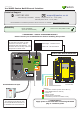
Suitability
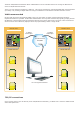
The interface plugs directly into
the TCP/IP Ethernet network via
a standard RJ45 connection box.
To next ACU
**IMPORTANT - THIS IS A NETWORK DEVICE**
Please contact your IT Administrator before installing this product
DHCP compatible
(xed IP recommended)
Connect over LAN, WAN or VPN
**IMPORTANT**
Apply power to the unit after connecting the RJ45
plug to a network point.
Switchable 120 Ohm resistors
DO NOT HARD WIRE IN RESISTORS
Reset to DHCP mode
To reset the unit, power up with
this button held down until the
‘heartbeat’ LED stops ashing. The
interface will now be fully reset and
will operate in DHCP mode.
1
2
3
4 5
6
LED key
1 - 120 ohm resistors (Active when LED on)
2 - Net2 RS485 data line activity
3 - Power on
4 - Ethernet data
5 - Ethernet line connection
6 - Heartbeat (connection to Net2 server)
Switch Right - Resistors active
Switch Left - Not Terminated
Paxton