PH3Z 13 SEER SINGLE-PACKAGED HEAT PUMP SYSTEM WITH R-22 REFRIGERANT SINGLE AND THREE PHASE 2-5 NOMINAL TONS (SIZES 024-060) Installation Instructions NOTE: _ Read the entire instruction manual before starting the installation. TABLE OF CONTENTS PAGE RECEIVING AND INSTALLATION Check Equipment Identify Unit .......0....00.00048. 2 2-7 .. 0.0.0... 00. eee eee 22... 2 ene 2 Inspect Shipment ..... 0.0.0... . eee eee 2 Provide Unit Support Slab Mount 2.0. 6c Ground Mount eee 0... 0. eee 2... 0.
Installation and servicing of this equipment can be hazardous due to mechanical and electrical components. Only trained and qualified personnel should install, repair, or service this equipment. Untrained personnel can perform basic maintenance functions such as cleaning and replacing air filters. All other operations must be performed by trained service personnel.
When designing and installing ductwork, consider the following: 4 CAUTION UNIT DAMAGE CONFIGURING DISCHARGE UNITS CE HAZARD ELECTRICAL components. Failure to follow injury or death. (VERTICAL) SHOCK HAZARD this warning could result in personal Before performing service or maintenance operations on the system, turn off main power to unit and install lockout tag. may be damaged.
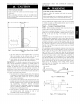
art u PH3Z024 PH3Z030 PH3Z036 PH3Z042 PH3Z048 PH3Z060 ELECTRICAL CHARACTERTSTICS 208-230-1-60 208-230-1-60 208-230-1-60 208-230-1-60 208-230-1-60 208-230-1-60 UNIT WT. Les. | KG. 293 | 133 324 | 147 377 fit 389 | 177 3ea_[ 175 433_[i97_[ pe [| [| [ | | UNIT HEIGHT A 30.13 [765] 34.13 [867] 42.13 toro) 42.13 (oT) 42.13 Trove) 42.73 trove) | | 14.0 14.0 [14.0 14.0 [4.0 44.0 | | X CENTER OF GRAVITY i (356) [ 19.0 [483] (356) [ 19.0 (483) (386) [19.0 (483) (356) | 19.0 (483) (3501 [19.
INDOOR THERMOSTAT power SOURCE ee eee DISCONNECT (UNIT AND. ELECTRIC cheer RUST-PROOF BASEPAN ames Power Wiring Contro! Wiring »»> ey | "= CONDENSATE CONNECTION Condenser Airflow Evaporator Airflow A08207 Fig.
Table 2 - Minimum Airflow for Safe Electric Heater Operation — Unit Size 024 030 036 042 048 060 Minimum Airflow (CFM) 5kW | 7.5kW | 10kW | 15kW | 20kW 500 600 600 600 600 600 650 B00. goo. goo. goo. goo. | | | | | 750 1050 1050. 1150. | 1050. | 1150. | 1050. | 1150. | 1050. | 1150. | 1200 1200 1200 1200 ELECTRICAL Failure to follow injury or death.
HEATER LOW VOLTAGE PLUG Thermostat and subbase Unit Control ower A05208 A05388 Fig. 11 - Control Connections (Sizes 048-060) Fig. 8 - Control Box Wiring PRE-START-UP UNIT GROUND CUANDO: GROUND SINGLE-PHASE 3-PHASE -~Teap [ |; ____ | RK CONNECTIONS CONNECTIONS |TODISCONNECT), TO DISCONNECT |PER NEC PER NEC L = ~R_veL bin nanny - 7 FIRE, EXPLOSION, HAZARD YEL~ Failure to follow this warning could injury or death and/or property damage.
c. Inspect all field- and factory-wiring connections. Be sure that connections are completed and tight. d. Ensure wires do not touch refrigerant tubing or sharp sheet metal edges. e. Inspect coil fins. If damaged during shipping and handling, carefully straighten fins with a fin comb. 4. Verity the following conditions: 4. When using an automatic changeover room thermostat, place both SYSTEM and FAN switches in AUTO positions.
Table 3 — Required Subcooling Model Required Subcooling FCC} Outdoor Ambient Temperature Size 75 048 049 060 . Charging (24) 82 (28) 85 (29) 95 15 20 61 56 924 141 14 69 64 59 972 156 80 15 10 65 1075 1124 31 28 26 170 Vat 184 194 86 89 91 94 81 84 86 89 16 79 81 84 V1 14 76 19 1172 1220 1268 1307 33 34 36 37 the “8 5 s 88 8 He eet .
Step 5 — Unit Controls COOLING All compressors have the following internal-protection controls. These units utilize a 2 stage indoor thermostat. With a first stage call for cooling (Y1), the indoor fan (low stage) energizes immediately whereas the contactor energizes after a 5 minute time delay (in case of an initial start-up) starting the compressor (low stage) and the outdoor fan motor.
FIELD hower an UNIT ONLY MAXIMUM WIRE SITE 2 AWG -— — atk SCHEMATIC CCH cee Oe yw DR ® DB BL Uy _ YEL £3 Wee one x EQUIP_GND = [2]| Ry [+———8RN cy oF VEL BLK FOR WIRING WITH reacccct 7 ELECTRIC HEATERS ' oe | SEE SCHEMATIC gf ON HEATER ACCESSORY." ow a Pye Ly I 2%) em | SEE NOTE TRAN eat Gh de tein th aa | MANUAL er BLU aie 7 / “teaCou IPM #6 3.2 YEL 12 on BRN ALLA | vec PLUG P< orn-vELU as | 230-160 pee BLK eal J Ne AMP.
FIELD cH PPLY OS rower SCHEMATIC : alkvam C BLK UNIT ONLY BLk MAXIMUM WIRE SIZE 2 AWG. Fe xT YEL oe 0 08 208/230-1-60 2 7 23)-—@3 YE EQUIP_GND can OFM YEL < 9 a = c 7 COMPRESSOR PLUG F am s © ~ YEL LK FOR WRING WHO sq ELECTRIC HEATERS en i SEE SCHEMATIC ey ON HEATER ACCESSORY. | L—— = —Ty Ze wal cal at ied | ES I It BLK ly eee a pil bi-e- Kor AC a ti i I i Le T see note #e—/ -T I ly i I i T 1 io it Lu! / | 3.2. ANP eee TRAN I | beeseeal.
FIELD UNIT ONLY MAXIMUM. WIRE SIZE 2 AWG con voice a Lk _— vEL SCHEMATIC alk vem yp ee co BLK ATH HEI DR @ DB “TO KEKE vet BLU or ' = | a ue ———BL K 230) @09) . ree ye EI ii i oa pli ~top--F Pipe em | € / NOTE TRANI MANUAL Gay 3.2 Fh eH r COM #6 1FM BRN AMP + SEE RESET NOTE 4 |! 1! 7 ~ i,t -y | Poo=acyR-+ we ee we L.
FIELD SCHEMATIC vont DR @ DB UNIT ONLY MAXIMUM. WIRE SIZE 2 AWG. = —— _ __ Gyrowee BLI YEL aHet TA AT HEB ml Wee ~ Lu 208/230-3-60 ss LA, a aoe «OUI ou on au YEL BLK == rex Pe A 1 = T; ON HEATER AccessoRY. |= L— = an 1! i4 rh BLK G30) Gd) cy [ft | | ; COMP SOLENOID . GRN-YEL ve | I l PLUG © 7 or | so {Op Lovet L FOR WRIG WITH ELECTRIC HEATERS SEE SCHEMATIC OFM TP \ cee 91> 28 SEE I TRANT NOTE “ BRN 3.
UNIT FAN Lv CONTROL PLUG BOARD CEP STEP 4 Ga BRN = .
Table 4 - Dry Coil Air Delivery* Horizontal Discharge (Deduct 10 percent for 208 Volt Operation) 230 VOLT HORIZONTAL DISCHARGE UNIT SIZE SPEED TAP ' 024 2 2 030 3 ' 036 2 3 042 4 ' 2 048 3 4 ' 2 060 3 4 AIR DELIVERY 0.1 0.2 0.3 EXTERNAL STATIC PRESSURE 0.4 0.5 0.6 (IN. WC) 0.7 Watts — 99 700 118 7130 0.8 0.9 1.
Table 5 — Cooling Charging Chart SUCTION LINE TEMPERATURE (°F) Suction Line Pressure (PSIG) oD Cy 52 54 56 59 61 64 67 7o | 73 | 76 | 79 | 82 | 85 | 89 92 45 51 55 60 64 69 55 — — 53 57 62 —_— —_— —_— —_ —_ _— —_— —_— —_ —_— 66 70 —_— —_— —_— —_ —_ _— —_— 65 — — — —_— 53 —_— 57 62 66 71 75 —_— —_— —_— —_ 75 _ _ _ _ —_ _ _ —_ 56 61 | 66 | 71 7 | — | — 85 — — — — — — — — —_— 53 58 63 67 72 —_— 95 —_— — —_— — — —
Only qualified service personnel should perform maintenance and 2. Remove the blower wheel from the housing: service procedures that require unit top removal. a. Loosen the set screw which secures the wheel to the Refer to the following top removal procedures: motor shaft. 1. Remove screws on unit top cover surface. (Save all screws.) b. Loosen the three mounting legs of the motor by 2. Remove screws on unit top cover flange. (Save all screws.
Step 4 — Outdoor Coil, Indoor Coil, and Condensate Drain Pan Inspect the condenser coil, evaporator coil, and condensate drain pan at least once each year. The coils are easily cleaned when dry; therefore, inspect and clean the coils either before or after each cooling season. Remove all obstructions, including weeds and shrubs, that interfere with the airflow through the condenser coil. Straighten bent fins with a fin comb.
COIL INDOOR COIL Eh Eh ERA |i ft | COMPRESSOR ACCUMULATOR ) = @) OUTDOOR ERA ao Ou Check Valves See A Open B Closed C Open D Closed FS strainer] © LEGEND Les Loss of Charge Switch A Acutrol Metering Device Check Valve (Arrow indicates direction of flow) HEATING CYCLE 1. Hot gas from compressor flows through the 4-way valve and is directed to the cooling liquid line check valve.
Table 9 — Troubleshooting Chart SYMPTOM CAUSE Compressor and outdoor fan REMEDY Power failure Call power company Fuse blown or circuit breaker tripped Replace fuse or reset circuit breaker Defective contactor, transformer, control relay, or high-pressure, lossof-charge or low-pressure switch Replace component Insufficient line voltage Determine cause and correct Incorrect or faulty wiring Check wiring diagram and rewire correctly Thermostat setting too low/too high Reset Thermostat setting F
START-UP CHECKLIST (REMOVE AND STORE IN JOB FILE) I. PRELIMINARY INFORMATION Model No Serial No Il. PRE-START-UP _____ Verify that all packing materials have been removed from unit. ____ Verify that condensate connection is installed per installation instructions. _____ Check ail electrical connections and terminals for tightness. _____ Check wire proximity to refrigerant tubes and sheet metal edges. ____ Check that indoor (indoor) air filter is clean and in place.