
LLC Gas/Oil Boilers Installation, Operation & Maintenance Manual
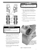
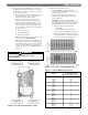

D. INSTALL COILS OR PLATES
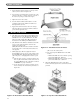
1. Remove the coil cover plates, gaskets and mounting
hardware, located in the Flue Box Carton.
2. Install tankless heaters, if used, in openings #1 and
#2. See Figure 2.10 and Table 2.2.
3. Place the cover plates and gaskets over any unused
heater openings. Place the cover plate with two 3/4"
NPT tappings on the upper flow port opening
(Position #2) of the Front Section.
E. HYDROSTATIC TEST THE BOILER
1. Install a drain valve in the Rear Section, Tapping 13.
See Figure 8.2.
2. Provide a water supply line to the boiler.
3. Plug all open tappings in the boiler.
4. Provide a means to vent air as the boiler fills.
5. Fill the boiler with water, venting air as water level
rises.
6. Pressurize boiler to:
• 75 psig for 50 psig sections.
• 120 psig for 80 psig sections.
• DO NOT EXCEED THESE PRESSURES.
a) Maintain pressure while checking all joints and
fittings for leaks.
7. After inspection is complete, drain the boiler and
remove plugs from tappings that are to be used.
17
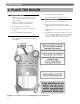
PLACE THE BOILER
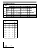
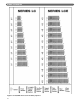
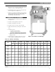
Table 2.2: Tankless Coil Ratings
LC-04
LC-05R
LC-05
LC-06
LC-07
LC-08
LC-09
LC-10
LC-11
LC-12
LCE-13
LCE-14
LCE-15
LCE-16
LCE-17
LCE-18
LCE-19
LCE-20
LCE-21
LCE-22
LCE-23
LCE-24
Model
GPM Location
5.5
5.62
5.75
6.25
6.5
7.0
7.25
7.5
8.0
–
–
–
–
–
–
–
–
–
–
–
–
–
2
2
2
2
2
2
2
2
2
–
–
–
–
–
–
–
–
–
–
–
–
–
GPM Location
–
6.5
7.0
7.75
8.5
9.25
10.0
10.75
11.50
12.25
13
13
13
13
13
13
13
13
13
13
13
13
–
2
2
2
2
2
2
2
2
2
2
2
2
2
2
2
2
2
2
2
2
2
GPM Location
–
–
–
–
13.0
13.75
14.5
15.5
16.5
17.5
18.0
18.75
19.5
20
20
20
20
20
20
20
20
20
–
–
–
–
2
2
2
2
2
2
2
2
2
2
2
2
2
2
2
2
2
2
GPM Location
8.0
9.0
10.0
12.0
13.0
14.0
14.5
15.0
16.0
–
–
–
–
–
–
–
–
–
–
–
–
–
1 & 2
1 & 2
1 & 2
1 & 2
1 & 2
1 & 2
1 & 2
1 & 2
1 & 2
–
–
–
–
–
–
–
–
–
–
–
–
–
GPM Location
–
9.5
10.5
13.0
15.5
17.5
20.0
21.5
23.5
24.5
26
26
26
26
26
26
26
26
26
26
26
26
–
1 & 2
1 & 2
1 & 2
1 & 2
1 & 2
1 & 2
1 & 2
1 & 2
1 & 2
1 & 2
1 & 2
1 & 2
1 & 2
1 & 2
1 & 2
1 & 2
1 & 2
1 & 2
1 & 2
1 & 2
1 & 2
GPM Location
–
–
–
–
15.5
18.0
20.0
22.5
24.5
27.0
29
31.5
33.5
35.5
37.5
39.5
40
40
40
40
40
40
–
–
–
–
1 & 2
1 & 2
1 & 2
1 & 2
1 & 2
1 & 2
1 & 2
1 & 2
1 & 2
1 & 2
1 & 2
1 & 2
1 & 2
1 & 2
1 & 2
1 & 2
1 & 2
1 & 2
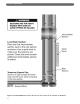
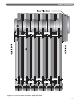
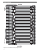
Figure 2.10: Tankless Coil Openings
Heater No.
X-1020
Heater No.
X-1021
Heater No.
X-1022
Two Heaters No.
X-1020
Two Heaters No.
X-1021
Two Heaters No.
X-1022
Above heater ratings are based on intermittent demand for water from 40
°F to 140°F with 200°F boiler water.
DANGER: Install mixing valve in hot water supply piping. Water temperature over 125°F can cause severe burns instantly or death from scalds.