Motherboard User’s Guide This publication, including photographs, illustrations and software, is under the protection of international copyright laws, with all rights reserved. Neither this guide, nor any of the material contained herein, may be reproduced without the express written consent of the manufacturer. The information in this document is subject to change without notice.
Motherboard User’s Guide Table of Contents Trademark ............................................................................................................ i Chapter 1: Introduction ..................................................................................... 1 Key Features .................................................................................................................... 1 Package Contents .......................................................................................
Motherboard User’s Guide Chapter 6: Trouble Shooting Tips ................................................................. 45 Start up problems during assembly ................................................................. 45 Start up problems after prolong use ................................................................ 46 Maintenance and care tips ............................................................................... 46 Notice: 1.
Motherboard User’s Guide Chapter 1 Introduction This motherboard has a socket AM2+/AM2 supporting the newest and advanced TM TM TM AMD PhenomTM II/AMD Phenom /Athlon 64 X2 Dual-Core/Athlon 64/ TM TM Sempron CPUs with 2000 MT/s Hyper Transport (HT) interface Speeds. This motherboard is based on NVIDIA® MCP61P/MCP61S that supports the Serial ATA interface for high-performance and mainstream desktop PCs, and the built-in USB 2.0 providing higher bandwidth, implementing USB 2.0 EHCI and USB 1.1 OHCI.
Motherboard User’s Guide Memory Support • Two 240-pin DIMM slots for DDR2 SDRAM memory modules • Supports Dual Channel DDR2 800/667/533/400 memory bus • Maximum installed memory is 16* GB (* Duo to the DRAM maximum size is 2 GB at present, the memory maximum size we have tested is 4 GB.
Chapter 1: Introduction Onboard I/O Ports • Two PS/2 ports for mouse and keyboard • One parallel port • One serial port • One VGA port • Four back-panel USB2.0 ports • One LAN port • Audio jacks for microphone, line-in and 6/8-channel (optional) line-out Fast Ethernet LAN • 10Base-T/100BASE-TX IEEE 802.3u fast Ethernet transceiver • Low-power mode • MII and 7-wire serial interface USB 2.0 • Compliant with Universal Serial Bus Specification Revision 2.
Motherboard User’s Guide Package Contents Your motherboard package ships with the following items: The motherboard The User’s Guide One diskette drive ribbon cable (optional) One IDE drive ribbon cable The Software support disk Optional Accessories You can purchase the following optional accessories for this motherboard.
Chapter 2: Motherboard Installation Chapter 2 Motherboard Installation To install this motherboard in a system, please follow these instructions in this chapter: Identify the motherboard components Install a CPU Install one or more system memory modules Make sure all jumpers and switches are set correctly Install this motherboard in a system chassis (case) Connect any extension brackets or cables to headers/connectors on the motherboard Install peripheral devices and make the appropriate conn
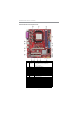
Motherboard User’s Guide Motherboard Components ITEM LABEL COMPONENTS Socket AM 2+/AM 2 for AM D PhenomTM II/AM D 1 2 3 4 5 6 7 8 9 10 11 12 13 14 15 16 17 18 19 20 CPU Socket PhenomTM/AM D X2 Dual-Core/AthlonTM 64/ DIM M 1~2 FDD PWR1 IDE1 SPK1 SATA1~4 CLR_CM OS PANEL1 USBPWR_F F_USB1~3 SYS_FAN SPDIFO1 CD_IN F_AUDIO PCI1~2 PCIEX1 PCIEX16 USBPWR_R PWR2 SempronTM processors 240-pin DDR2 SDRAM slots Floppy disk drive connector Standard 24-pin ATX power connector Primary IDE connector Speaker header Se
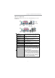
Chapter 2: Motherboard Installation I/O Ports (optional) The illustration below shows a side view of the built-in I/O ports on the motherboard. PS/2 Mouse Use the upper PS/2 port to connect a PS/2 pointing device. PS/2 Keyboard Use the low er PS/2 port to connect a PS/2 keyboard. Parallel Port (LPT) Use the Parallel port to connect printers or other parallel communications devices. Serial Port (COM1) Use the COM port to connect serial devices such as mice or fax/modems.
Motherboard User’s Guide Installing the Processor This motherboard has an AM2+/AM2 processor socket. When choosing a processor, consider the performance requirements of the system. Performance is based on the processor design, the clock speed and system bus frequency of the processor, and the quantity of internal cache memory and external cache memory. CPU Installation Procedure Follow these instructions to install the CPU: 1 2 3 4 5 6 Unhook the locking lever of the CPU socket.
Chapter 2: Motherboard Installation Installing Memory Modules This motherboard accommodates two 240-pin DIMM sockets (Dual Channel Memory Module) for unbuffered DDR2 800/667/533/400 memory modules (Double Data Rate SDRAM), and maximum 16* GB installed memory. Over its predecessor, DDR2-SDRAM offers greater bandwidth and density in a smaller package along with a reduction in power consumption.
Motherboard User’s Guide Note for dual-channel DDR2: 1. You CAN NOT use only one DIMM2 for it might cause the system shutdown. 2. You need to use DIMM1 and DIMM2 with the same size of memory modules. Jumper Settings Connecting two pins with a jumper cap is SHORT; removing a jumper cap from these pins, OPEN. CLR_CMOS: Clear CMOS Jumper Use this jumper to clear the contents of the CMOS memory.
Chapter 2: Motherboard Installation USBPWR_R: REAR USB PS/2 POWER SELECT Jumper Use this jumper to set the Rear USB PS/2 Power function. 1 USBPWR_R Function VCC5 VCC5_DUAL Jum per Setting Short Pins 1-2 Short Pins 2-3 Note:1. Make sure the power supply provides enough VCC5_DUAL voltage before selecting the VCC5_DUAL function. 2. It is required that users place the USBPWR_F & USBPWR_R cap onto 2-3 pin rather than 1-2 pin as default if you want to wake up the computer by USB/PS2 KB/Mouse.
Motherboard User’s Guide Here is a list of the PANEL1 pin assignments. Pin 1 3 5 7 9 Signal HD_LED_P(+) HD_LED_N(-) RESET_SW_N(-) RESET_SW_P(+) RSVD Pin 2 4 6 8 10 Signal FP PWR/SLP(+) FP PWR/SLP(-) POWER_SW_P(+) POWER_SW_N(-) KEY Connecting Optional Devices Refer to the following for information on connecting the motherboard’s optional devices: SPK1: Speaker Header Connect the cable from the PC speaker to the SPK1 header on the motherboard.
Chapter 2: Motherboard Installation F_USB1~3: Front Panel USB Headers The motherboard has USB ports installed on the rear edge I/O port array. Additionally, some computer cases have USB ports at the front of the case. If you have this kind of case, use auxiliary USB headers F_USB1~3 to connect the front-mounted ports to the motherboard. Here is a list of USB pin assignments.
Motherboard User’s Guide Install Other Devices Install and connect any other devices in the system following the steps below. Floppy Disk Drive The motherboard ships with a floppy disk drive cable that can support one or two drives. Drives can be 3.5" or 5.25" wide, with capacities of 360K, 720K, 1.2MB, 1.44MB, or 2.88MB. Install your drives and connect power from the system power supply. Use the cable provided to connect the drives to the floppy disk drive connector FDD.
Chapter 2: Motherboard Installation Serial ATA Devices The Serial ATA (Advanced Technology Attachment) is the standard interface for the IDE hard drives, which is designed to overcome the design limitations while enabling the storage interface to scale with the growing media rate demands of PC platforms. It provides you a faster transfer rate of 3.0 Gb/s. If you have installed a Serial ATA hard drive, you can connect the Serial ATA cables to the Serial ATA hard drive or the connector on the motherboard.
Motherboard User’s Guide Here is a list of CD_IN pin assignments. Pin 1 2 3 Signal CD_L GND GND 4 CD_R Expansion Slots This motherboard has one PCI Ex16 slot (MCP61S only supports PCI Express x8), one PCI Ex1 slot and two 32-bit PCI slots.
Chapter 2: Motherboard Installation Follow the steps below to install an PCI Express x16/PCI Express x1/PCI expansion card. 1. Locate the PCI Express x16, PCI Express x1 and PCI slots on the mainboard. 2. Remove the blanking plate of the slot from the system chassis. 3. Install the edge connector of the expansion card into the slot. Ensure the edge connector is correctly seated in the slot. 4. Secure the metal bracket of the card to the system chassis with a screw.
Motherboard User’s Guide Chapter 3 BIOS Setup Utility Introduction The BIOS Setup Utility records settings and information of your computer, such as date and time, the type of hardware installed, and various configuration settings. Your computer applies the information to initialize all the components when booting up and basic functions of coordination between system components. If the Setup Utility configuration is incorrect, it may cause the system to malfunction.
Chapter 3: BIOS Setup Utility Some options on the main menu page lead to tables of items with installed values that you can use cursor arrow keys to highlight one item, and press PgUp and PgDn keys to cycle through alternative values of that item. The other options on the main menu page lead to dialog boxes requiring your answer OK or Cancel by selecting the [OK] or [Cancel] key. If you have already changed the setup utility, press F10 to save those changes and exit the utility.
Motherboard User’s Guide f Primary IDE Master/Slave, SATA 1~4 Your computer has one IDE channel which can be installed with one or two devices (Master and Slave). In addition, this motherboard supports four SATA channels and each channel allows one SATA device to be installed. Use these items to configure each device on the IDE channel. CMOS SETUP UTILITY – Copyright (C) 1985-2005, American Megatrends, Inc.
Chapter 3: BIOS Setup Utility IDE BusMaster (Enabled) This item enables or disables the DMA under DOS mode. We recommend you to leave this item at the default value. Drive A (1..44 MB 31/2” ) This item defines the characteristics of any diskette drive attached to the system. You can connect one or two diskette drives. Press to return to the main menu setting page. Advanced Setup Page This page sets up more advanced information about your system. Handle this page with caution.
Motherboard User’s Guide Boot Up Numlock Status (On) This item defines if the keyboard Num Lock key is active when your system is started. APIC Mode (Enabled) This item allows you to enable or disable the APCI (Advanced Programmable Interrupt Controller) mode. APIC provides symmetric multi-processing (SMP) for systems, allowing support for up to 60 processors.
Chapter 3: BIOS Setup Utility fRemovable Drives (Press Enter) Scroll to this item and press to view the following screen: CMOS Setup Utility - Copyright (C) 1985-2005, American Megatrends, Inc. Removable Drives Help Item Removable Drives 1st Drive 1st FLOPPY DRIVE m n l k : Move Specifies the boot sequence from the available devices. Enter : Select +/-/: Value F10: Save F1:General Help F9: Optimized Defaults ESC: Exit Press to return to the Advanced setup page.
Motherboard User’s Guide Advanced Chipset Setup Page This page sets up more advanced information about your system. Handle this page with caution. Any changes can affect the operation of your computer. CMOS Setup Utility - Copyright (C) 1985-2005, American Megatrends, Inc.
Chapter 3: BIOS Setup Utility Integrated Peripherals Page This page sets up some parameters for peripheral devices connected to the system. CMOS Setup Utility - Copyright (C) 1985-2005, American Megatrends, Inc. Integrated Peripherals Help Item Onboard IDE Controller Serial-ATA 0 SATA Mode Select Enabled Enabled SATA Mode f nVidia RAID Setup Press Enter PRIMARY: enables only the Primary IDE Controller.
Motherboard User’s Guide Onboard AUDIO Function (Auto) Use this item to enable or disable the onboard audio device. OnBoard LAN Function (Auto) Use this item to enable or disable the onboard LAN function. OnBoard LAN Boot ROM (Disabled) Use this item to enable or disable the booting from the onboard LAN or a network add-in card with a remote boot ROM installed. Serial Port1 Address (3F8/IRQ4) Use this item to enable or disable the onboard COM1 serial port, and to assign a port address.
Chapter 3: BIOS Setup Utility ACPI Suspend Type (S3(STR)) Use this item to define how your system suspends. In the default, S3, the suspend mode is a suspend to RAM, i.e, the system shuts down with the exception of a refresh current to the system memory. PWRON After PWR-Fail (Power Off) This item enables your computer to automatically restart or return to its operating status.
Motherboard User’s Guide PCI/PnP Setup Page Scroll to this item and press to view the following screen: This page sets up some parameters for devices installed on the PCI bus and those utilizing the system plug and play capability. CMOS Setup Utility - Copyright (C) 1985-2005, American Megatrends, Inc.
Chapter 3: BIOS Setup Utility f Smart Fan Function Scroll to this item and press to view the following screen: CMOS Setup Utility - Copyright (C) 1985-2005, American Megatrends, Inc. Smart Fan Function SMART Fan Control SMART Fan Start PWM value SMART Fan start TEMP.
Motherboard User’s Guide • CPU Core • VDIMM • CPU Tcontrol • CPU Fan Speed • System Temperature Press to return to the main menu setting page. Frequency/Voltage Control Page This page enables you to set the clock speed and system bus for your system. The clock speed and system bus are determined by the kind of processor you have installed in your system. CMOS Setup Utility - Copyright (C) 1985-2005, American Megatrends, Inc.
Chapter 3: BIOS Setup Utility Load Default Settings This option opens a dialog box to ask if you are sure to install optimized defaults or not. You select [OK], and then , the Setup Utility loads all default values; or select [Cancel], and then , the Setup Utility does not load default values. Supervisor Password This page helps you install or change a password. CMOS Setup Utility - Copyright (C) 1985-2005, American Megatrends, Inc.
Motherboard User’s Guide User Password This page helps you install or change a password. CMOS Setup Utility - Copyright (C) 1985-2005, American Megatrends, Inc. User Password Help Item User Password : Not Installed Install or Change the password. Change User Password m n l k : Move Enter : Select F1:General Help Press Enter +/-/: Value F10: Save F9: Optimized Defaults ESC: Exit User Password (Not Installed) This item indicates whether a user password has been set.
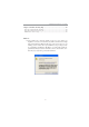
Chapter 4: Software & Applications Chapter 4 Software & Applications Introduction This chapter describes the contents of the support DVD-ROM/CD-ROM that comes with the motherboard package. The support DVD-ROM/CD-ROM contains all useful software, necessary drivers and utility programs to properly run our products. More program information is available in a README file, located in the same directory as the software. To run the support disk, simply insert the disk into your DVD-ROM/CD-ROM drive.
Motherboard User’s Guide The Browse CD button is a standard Windows command that you can check the contents of the disc with the Windows file browsing interface. The Exit button closes the Auto Setup window. To run the program again, reinsert the DVD-ROM/CD-ROM disc in the drive; or click the DVD-ROM/CD-ROM driver from the Windows Explorer, and click the Setup icon. The Application button brings up a software menu. It shows the bundled software that this mainboard supports.
Chapter 4: Software & Applications 3 The support software will automatically install. Once any of the installation procedures start, software is automatically installed in sequence. You need to follow the onscreen instructions, confirm commands and allow the computer to restart as few times as needed to complete installing whatever software you selected. When the process is finished, all the support software will be installed and start working.
Motherboard User’s Guide Chapter 5 Setting Up NVIDIA RAID Configuration There are two ways to setup NVIDIA RAID Configuration: one is to create a RAID 1 Array for backup or a RAID 0 Array for increased performance just by adding additional disk array without changing the original OS (Non-Bootable RAID Array); while the other is to configure the RAID Array disks when reinstalling the OS (Bootable RAID Array).
Chapter 5: Setting Up NVIDIA RAID Configuration 3 From the Integrated Peripherals Window, globally set SATA Mode select to RAID Mode (see Figure 1.2). 4 Press F10 to save the configuration and exit (F10 is the navigation key to save the current configuration and exit setup in BIOS setting). The PC reboots. Installing the NVIDIA RAID Software Under Windows This section describes how to run the setup application and install the RAID software.
Motherboard User’s Guide Setting Up a Boota b le RAID Ar Bootab Arrr a y This section explains how to configure a bootable NVIDIA RAID array. Setting Up the BIOS 1 Start your computer, then press Delete to enter the BIOS setup. The BIOS CMOS Setup Utility screen appears. Figure 1.4 2 BIOS CMOS Setup Utility Main Screen Use the arrow keys to select Integrated Peripherals (see Figure 1.4), then press Enter. The Integrated Peripherals screen (or a screen similar to it) appears. Figure 1.
Chapter 5: Setting Up NVIDIA RAID Configuration 4 Press F10 to save the configuration and exit. The PC reboots. 5 Enter the RAID BIOS Setup by pressing F10 when prompted, and proceed to set up the NVIDIA RAID BIOS as described in the next section. Configuring the NVIDIA RAID BIOS The NVIDIA RAID BIOS set up lets you choose the RAID type and which hard drives you want to make part of the array. Entering the RAID BIOS Setup: 1 Wait until you see the RAID software prompting you to press F10.
Motherboard User’s Guide The NVIDIA RAID Utility—Define a New Array screen appears (Figure 1.7). Figure 1.7 MediaShield BIOS By default, RAID Mode is set to Mirroring and Striping Block is set to Optimal. Using the Define a New Array Screen If necessary, press the tab key to move from field to field until the appropriate field is highlighted. • Selecting the RAID Mode By default, this is set to Mirroring.
Chapter 5: Setting Up NVIDIA RAID Configuration Figure 1.8 illustrates the Define a New Array screen after one disk have been assigned as RAID 0 array disk. Figure 1.8 MediaShield BIOS—Array Disks Assigned Completing the RAID BIOS Setup 1 After assigning your RAID array disk, press F7. The Clear disk array prompt appears. Figure 1.
Motherboard User’s Guide 2 Press Y to clear the disk data. The Array List screen appears, where you can review the RAID arrays that you have set up. Figure 1.10 Array List Window 3 Use the arrow keys to select the array that you want to set up, then press B to specify the array as bootable. 4 Press Enter to view and verify details.
Chapter 5: Setting Up NVIDIA RAID Configuration Installing the RAID Drivers Your system may come with a Windows install disk that already includes NVIDIA RAID drivers. If so, then this section is not relevant. If that is not the case (or you are trying to install a new version of Windows), then you will need an NVIDIA RAID driver F6 install floppy. Check to see if one came with your system. If not, you can create one by downloading the appropriate driver package and following the steps in this section.
Motherboard User’s Guide b Select “NVIDIA RAID CLASS DRIVER (required)” and then press Enter. c Press S again at the Specify Devices screen, then press Enter. d Select “NVIDIA NForce Storage Controller (required)” and then press Enter. The following Windows Setup screen appears listing both drivers:. Figure 1.13 5 Windows Setup—NVIDIA drives listed Press Enter to continue with Windows Installation.
Chapter 6: Trouble Shooting Tips Chapter 6 Trouble Shooting Tips Star t up pr ob lems during assemb prob oblems assembll y After assembling the PC for the first time you may experience some start up problems. Before calling for technical support or returning for warranty, this chapter may help to address some of the common questions using some basic troubleshooting tips. a) System does not power up and the fans are not running. 1.
Motherboard User’s Guide c) The PC suddenly shuts down while booting up. 1. The CPU may experience overheating so it will shutdown to protect itself. Ensure the CPU fan is working properly. 2. From the BIOS setting, try to disable the Smartfan function to let the fan run at default speed. Doing a Load Optimised Default will also disable the Smartfan. Star t up pr ob lems after pr olong use prob oblems prolong After a prolong period of use your PC may experience start up problems again.
If fail, contact RMA CLR CMOS and restart. Yes Halt at POST screen? Yes Check if monitor has display Yes Check if Power Supply Unit (PSU) is working Power Bu on is pressed but PC fails to start. CMOS setup error, - need to CLRCMOS. HDD problem.