Motherboard User’s Guide This publication, including photographs, illustrations and software, is under the protection of international copyright laws, with all rights reserved. Neither this guide, nor any of the material contained herein, may be reproduced without the express written consent of the manufacturer. The information in this document is subject to change without notice.
Motherboard User’s Guide Table of Contents Trademark ............................................................................................................ i Chapter 1: Introduction ..................................................................................... 1 Key Features .................................................................................................................... 1 Package Contents .......................................................................................
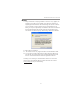
Motherboard User’s Guide Notice: 1. Owing to Microsoft’s certifying schedule is various to every supplier, we might have some drivers not certified yet by Microsoft. Therefore, it might happen under Windows XP that a dialogue box (shown as below) pops out warning you this software has not passed Windows Logo testing to verify its compatibility with Windows XP. Please rest assured that our RD department has already tested and verified these drivers.
Motherboard User’s Guide Chapter 1 Introduction This motherboard has a Socket-AM2 supporting the newest and advanced AMD Sempron/Athlon 64/Athlon 64 X2 Dual-Core/Athlon 64 FX with HyperTransport Technology processors and Front-Side Bus (FSB) speeds up to1000 MHz. It integrates the SiS761GX Northbridge and SiS965L Southbridge that supports the built-in USB 2.0 providing higher bandwidth, implementing Universal Serial Bus Specification Revision 2.0.
Motherboard User’s Guide • • • PCI 2.3 Specification Compliance Integrated Multithreaded I/O Link Mastering Multithread I/O Link Mastering with Read/Write Concurrent and Read/ Read Pipeline Transaction Memory Support • Two 240-pin DIMM sockets for DDR SDRAM memory modules • Supports DDR2 800/667/533/400 memory bus • Maximum installed memory is 16 GB Expansion Slots • One PCI Express x1 slot • One PCI Express x16 slot • Two 32-bit PCI slots for PCI 2.
Chapter 1: Introduction Fast Ethernet LAN (optional) • Supports 10BASE-T/100BASE-TX IEEE 802.3u fast Ethernet transceiver • Integrated voltage regulator to allow operation from a single 3.3 V/2.5V supply source • Supports MII and 7-wire serial interface • Supports low-power mode USB 2.0 • Compliant with Universal Serial Bus Specification Revision 2.0 • Compliant with Intel’s Enhanced Host Controller Interface Specification Revision 1.
Motherboard User’s Guide Package Contents Your motherboard package ships with the following items: The motherboard The User’s Guide One diskette drive ribbon cable (optional) One IDE drive ribbon cable The Software support CD Optional Accessories You can purchase the following optional accessories for this motherboard. The Extended USB module The CNR v.
Chapter 2: Motherboard Installation Chapter 2 Motherboard Installation To install this motherboard in a system, please follow these instructions in this chapter: Identify the motherboard components Install a CPU Install one or more system memory modules Make sure all jumpers and switches are set correctly Install this motherboard in a system chassis (case) Connect any extension brackets or cables to headers/connectors on the motherboard Install peripheral devices and make the appropriate conn
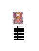
Motherboard User’s Guide Motherboard Components ITEM LABEL COMPONENTS Socket AM2 for AMD Athlon 64/Athlon 64 X2 Dual-Core/Athlon 64 FX CPUs 240-pin DDR2 SDRAM sockets 1 CPU Socket 2 DDRII1~2 3 IR1 Infrared header 4 CPU_FAN1 CPU Fan connector(4 PIN) 5 PWR1 Standard 24-Pin ATX Pow er connector 6 FDD1 Floppy Disk Drive connector 7 IDE1 Primary IDE connector 8 IDE2 Secondary IDE connector 9 F_USB1/2 Front Panel USB headers 10 SATA1/2 Serial ATA connectors 11 PANEL1 Front Panel
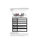
Chapter 2: Motherboard Installation I/O Ports The illustration below shows a side view of the built-in I/O ports on the motherboard. PS/2 Mouse Use the upper PS/2 port to connect a PS/2 pointing device. PS/2 Keyboard Use the lower PS/2 port to connect a PS/2 keyboard. Parallel Port (LPT1) Use the Parallel port to connect printers or other parallel communications devices. Serial Port (COM1) Use the COM port to connect serial devices such as mice or fax/modems.
Motherboard User’s Guide CPU Installation Procedure Follow these instructions to install the CPU: 1 2 3 4 5 6 Unhook the locking lever of the CPU socket. Pull the locking lever away from the socket and raising it to the upright position. Match the pin1 corner marked as the beveled edge on the CPU with the pin1 corner on the socket. Insert the CPU into the socket. Do not use force. Push the locking lever down and hook it under the latch on the edge of socket. Apply thermal grease to the top of the CPU.
Chapter 2: Motherboard Installation Over its predecessor, DDR2-SDRAM offers greater bandwidth and density in a smaller package along with a reduction in power consumption. In addition, DDR2SDRAM offers new features and functions that enable a higher clock rate and data rate operations of 400 MHz, 533 MHz 667 MHz and 800 MHz. DDR2 transfers 64 bits of data twice every clock cycle. Memory Module Installation Procedure These modules can be installed with up to 16 GB system memory.
Motherboard User’s Guide Note for dual-channel DDR2: 1. You CAN NOT use only one DIMM2 for it might cause the system shutdown. 2. You need to use DIMM1 and DIMM2 with the same size of memory modules. Jumper Settings Connecting two pins with a jumper cap is SHORT; removing a jumper cap from these pins, OPEN. CLR_CMOS1: Clear CMOS Jumper Use this jumper to clear the contents of the CMOS memory.
Chapter 2: Motherboard Installation Install The Motherboard Install the motherboard in a system chassis (case). The board is a Micro ATX size motherboard. You can install this motherboard in an ATX case. Make sure your case has an I/O cover plate matching the ports on this motherboard. Install the motherboard in a case. Follow the case manufacturer’s instructions to use the hardware and internal mounting points on the chassis.
Motherboard User’s Guide Connecting Optional Devices Refer to the following for information on connecting the motherboard’s optional devices: SPK1: Speaker Header Connect the cable from the PC speaker to the SPK1 header on the motherboard. Pin 1 2 3 4 Signal +5V NC GND SPKR F_AUDIO1: Front Panel Audio Header This header allows the user to install auxiliary front-oriented microphone and lineout ports for easier access.
Chapter 2: Motherboard Installation F_USB1~2: Front Panel USB Headers The motherboard has USB ports installed on the rear edge I/O port array. Additionally, some computer cases have USB ports at the front of the case. If you have this kind of case, use auxiliary USB headers F_USB1~2 to connect the front-mounted ports to the motherboard. Here is a list of USB pin assignments.
Motherboard User’s Guide Install Other Devices Install and connect any other devices in the system following the steps below. Floppy Disk Drive The motherboard ships with a floppy disk drive cable that can support one or two drives. Drives can be 3.5" or 5.25" wide, with capacities of 360K, 720K, 1.2MB, 1.44MB, or 2.88MB. Install your drives and connect power from the system power supply. Use the cable provided to connect the drives to the floppy disk drive connector FDD1.
Chapter 2: Motherboard Installation If you want to install more IDE devices, you can purchase a second IDE cable and connect one or two devices to the Secondary IDE channel connector IDE2 on the motherboard. If you have two devices on the cable, one must be Master and one must be Slave.
Motherboard User’s Guide Here is a list of CD_IN1 pin assignments. Pin 1 2 3 Signal CD IN L GND GND 4 CD IN R Expansion Slots This motherboard has one PCI Express x16, one PCI Express x1, one CNR and two 32-bit PCI slots.
Chapter 2: Motherboard Installation Follow the steps below to install an PCI Express x16/ PCI Express x1/CNR/PCI expansion card. 1. Locate the PCI Express x16, PCI Express x1, CNR or PCI slots on the mainboard. 2. Remove the blanking plate of the slot from the system chassis. 3. Install the edge connector of the expansion card into the slot. Ensure the edge connector is correctly seated in the slot. 4. Secure the metal bracket of the card to the system chassis with a screw.
Motherboard User’s Guide Chapter 3 BIOS Setup Utility Introduction The BIOS Setup Utility records settings and information of your computer, such as date and time, the type of hardware installed, and various configuration settings. Your computer applies the information to initialize all the components when booting up and basic functions of coordination between system components. If the Setup Utility configuration is incorrect, it may cause the system to malfunction.
Chapter 3: BIOS Setup Utility Some options on the main menu page lead to tables of items with installed values that you can use cursor arrow keys to highlight one item, and press PgUp and PgDn keys to cycle through alternative values of that item. The other options on the main menu page lead to dialog boxes requiring your answer OK or Cancel by selecting the [OK] or [Cancel] key. If you have already changed the setup utility, press F10 to save those changes and exit the utility.
Motherboard User’s Guide Advanced Setup Page This page sets up more advanced information about your system. Handle this page with caution. Any changes can affect the operation of your computer. CMOS Setup Utility – Copyright (C) 1985-2005, American Megatrends, Inc.
Chapter 3: BIOS Setup Utility Spread Spectrum If you enable spread spertrum, it can significantly reduce the EMI (ElectroMagnetic interface) generated by the system. Features Setup Page This page sets up some parameters for peripheral devices connected to the system. CMOS Setup Utility – Copyright (C) 1985-2005, American Megatrends, Inc.
Motherboard User’s Guide ECP Mode DMA Channel This item assigns a DMA channel to the parallel port. Parallel Port IRQ Use this item to assign IRQ to the parallel port. OnBoard PCI IDE Controller Use this item to enable or disable both of the onboard Primary and Secondary IDE channels. OnBoard PCI S-ATA Controller Use this item to enable the onboard PCI SATA Controller. Onboard AC97 Audio DEVICE This item enables or disables the AC’97 audio chip.
Chapter 3: BIOS Setup Utility Power Management Setup Page This page sets some parameters for system power management operation. CMOS Setup Utility – Copyright (C) 1985-2005, American Megatrends, Inc. ACPI Aware O/S Power Management Suspend mode Suspend Time Out Resume On RTC Alarm Resume On KeyBoard Keyboard Power On Help Item Yes Enabled S1 Disabled Disabled Disabled Disabled Enable /Disable ACPI support for Operating System. ENABLE: If OS supports ACPI.
Motherboard User’s Guide LAN/Ring Power On The system can be turned off with a software command. If you enable this item, the system can automatically resume if there is an incoming call on the Modem/ Ring, or traffic on the network adapter. You must use an ATX power supply in order to use this feature. PCI / Plug and Play Setup Page This page sets up some parameters for devices installed on the PCI bus and those utilizing the system plug and play capability.
Chapter 3: BIOS Setup Utility BIOS Security Features Setup Page This page helps you install or change a password. CMOS Setup Utility – Copyright (C) 1985-2005, American Megatrends, Inc. BIOS Security Features Help Item Security Settings Install or Change the password.
Motherboard User’s Guide CPU Type This item shows the type of the CPU installed in your system. CPU OVERCLOCK This item decides the CPU over-clocking function installed in your system. If the over-clocking fails, please turn off the system power. And then, hold the PageUp key (similar to the Clear CMOS function) and turn on the power, the BIOS will recover the safe default. DIMM Voltage Adjust Function This item enables or disables users to adjust DIMM voltage.
Chapter 3: BIOS Setup Utility FANs & Voltage Measurements These items indicate cooling fan speeds in RPM and the various system voltage measurements. CPU/SYS FAN Speed This item displays CPU/ system speed measurement. CPU/System Temperature This item displays CPU/ system temperature measurements. Load Optimal Defaults This option opens a dialog box to ask if you are sure to install optimized defaults or not.
Motherboard User’s Guide Chapter 4 Software & Applications Introduction This chapter describes the contents of the support CD-ROM that comes with the motherboard package. The support CD-ROM contains all useful software, necessary drivers and utility programs to properly run our products. More program information is available in a README file, located in the same directory as the software. To run the support CD, simply insert the CD into your CD-ROM drive.
Chapter 4: Software & Applications contents of the disc with the Windows file browsing interface. The Exit button closes the Auto Setup window. To run the program again, reinsert the CD-ROM disc in the drive; or click the CD-ROM driver from the Windows Explorer, and click the Setup icon. The Application button brings up a software menu. It shows the bundled software that this mainboard supports. The ReadMe brings you to the Install Path where you can find out path names of software driver.
Motherboard User’s Guide 3 The support software will automatically install. Once any of the installation procedures start, software is automatically installed in sequence. You need to follow the onscreen instructions, confirm commands and allow the computer to restart as few times as needed to complete installing whatever software you selected. When the process is finished, all the support software will be installed and start working.