This publication, including all photographs, illustrations and software, is protected under international copyright laws, with all rights reserved. Neither this manual, nor any of the material contained herein, may be reproduced without the express written consent of the manufacturer. The information in this document is subject to change without notice.
Table of Contents I Trademark ..................................................................................... I Static Electricity Precautions.................................................III Pre-Installation Inspection .....................................................III Chapter 1: Introduction................................................................1 Key Features ............................................................................2 Package Contents..............................
Static Electricity Precautions Static electricity could damage components on this mainboard. Take the following precautions while unpacking this mainboard and installing it in a system. 1. Don’t take this mainboard and components out of their original static-proof package until you are ready to install them. 2. While installing, please wear a grounded wrist strap if possible. If you don’t have a wrist strap, discharge static electricity by touching the bare metal of the system chassis. 3.
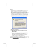
Notice: 1. Owing to Microsoft’s certifying schedule is various to every supplier, we might have some drivers not certified yet by Microsoft. Therefore, it might happen under Windows XP that a dialogue box (shown as below) pop out warning you this software has not passed Windows Logo testing to verify its compatibility with Windows XP. Please rest assured that our RD department has already tested and verified these drivers. Just click the “Continue Anyway” button and go ahead the installation. 2. USB 2.
Chapter 1 Introduction This mainboard has a Socket-370 processor socket for the Intel FCPGA Celeron, FCPGA Pentium III or VIA C3 Samuel2 processor with front-side bus speed up to 133MHz. This mainboard integrates the VIA CLE266 Northbridge and 8235 Southbridge chipsets that support DDR 266MHz, Ultra DMA 33/66/100/133 function and remarkably high system performance under all types of system operations It supports built-in USB 2.0 providing higher bandwidth.
Key Features The key features of this mainboard include: Socket-370 Processor Support ♦ Supports the Intel FCPGA Celeron, FCPGA Pentium III or VIA C3 Samuel2 processors ♦ Supports 133 MHz Front-Side Bus Chipset There are VIA CLE266 Northbridge and 8235 Southbridge in this chipset in accordance with an innovative and scalable architecture with proven reliability and performance.
Onboard IDE channels ♦ Primary and Secondary PCI IDE channels ♦ Support for PIO (programmable input/output) modes ♦ Support for Multiword DMA modes ♦ Support for Bus Mastering and Ultra DMA ATA 33/66/100/133 modes Power Supply and Power Management ♦ ATX power supply connector ♦ Meets ACPI 1.0B and PCI Bus Power Management 1.
Onboard I/O Ports The mainboard has a full set of I/O ports and connectors: ♦ Two PS/2 ports for mouse and keyboard ♦ One serial port ♦ One VGA port ♦ One parallel port ♦ Six USB2.
BIOS Firmware This mainboard uses AMI BIOS that enables users to configure many system features including the following: ♦ Hard drives, diskette drives, and peripherals ♦ Power management ♦ CPU parameters and memory timing ♦ Hardware monitoring parameters The firmware can also be used to set parameters for different processor clock speeds. Bundled Software ♦ PC-Cillin2002 provides automatic virus protection under Windows 98/ME/NT/2000/XP ♦ Adobe Acrobat Reader V5.0 is the software to help users read .
Package Contents Your mainboard package ships with the following items: The mainboard The User’s Manual One diskette drive ribbon cable (optional) One IDE drive ribbon cable The Software support CD Optional Accessories You can purchase the following optional accessories for this mainboard. The Extended USB module The CNR v.
Chapter 2 Mainboard Installation To install this mainboard in a system, please follow these instructions in this chapter: Identify the mainboard components Install one or more system memory modules Make sure all jumpers and switches are set correctly Install this mainboard in a system chassis (case) Connect any extension brackets or cables to connectors on the mainboard Install peripheral devices and make the appropriate connections to connectors on the mainboard. Note: 1.
Mainboard Components Use the diagram below to identify the major components on the mainboard. I/O Ports The illustration below shows a side view of the built-in I/O ports on the mainboard.
PS/2 Mouse PS/2 Keyboard LPT1 COM1 VGA LAN Port (optional) USB Ports Audio Ports Use the upper PS/2 port to connect a PS/2 pointing device. Use the lower PS/2 port to connect a PS/2 keyboard. Use LPT1 to connect printers or other parallel communications devices. Use the COM port to connect serial devices such as mice or fax/modems. COM1 is identified by the system as COM1. Use the VGA port to connect VGA devices. Connect an RJ-45 jack to the LAN port to connect your computer to the Network.
CPU Installation Procedure Follow these instructions to install the CPU: Pin 1 SOCKET-370 CPU_FAN 1 1. Unhook the locking lever of the CPU socket. Pull the locking lever away from the socket and raising it to the upright position. 2. Match the pin1 corner marked as the beveled edge on the CPU with the pin1 corner on the socket. Insert the CPU into the socket. Do not use force. 3. Push the locking lever down and hook it under the latch on the edge of socket. 4. Apply thermal grease to the top of the CPU.
DDR SDRAM is a type of SDRAM that supports data transfers on both edges of each clock cycle (the rising and falling edges), effectively doubling the memory chip’s data throughput. DDR DIMMs can synchronously work with 200 MHz or 266 MHz memory bus. DIMM1 DIMM2 Installation Procedure These modules can be installed with up to 1 GB system memory. Refer to the following to install the memory module. 1. Push down the latches on both sides of the DIMM socket. 2. Align the memory module with the socket.
Jumper Settings Connecting two pins with a jumper cap is SHORT; removing a jumper cap from these pins, OPEN. JBAT1 1 Jumper JBAT1: Clear CMOS Memory Use this jumper to clear the contents of the CMOS memory. You may need to clear the CMOS memory if the settings in the Setup Utility are incorrect and prevent your mainboard from operating. To clear the CMOS memory, disconnect all the power cables from the mainboard and then move the jumper cap into the CLEAR setting for a few seconds.
SYSTEM_FAN 1 ATX1 1 PANEL1 Connect the power connector from the power supply to the ATX1 connector on the mainboard. If there is a cooling fan installed in the system chassis, connect the cable from the cooling fan to the SYSTEM_FAN fan power connector on the mainboard. Connect the case switches and indicator LEDs to the PANEL1 connector.
SPK1: Speaker Connector Connect the cable from the PC speaker to the SPK1 connector on the mainboard. Pin 1 3 Signal SPKR GND Pin 2 4 Signal NC +5V AUDIO2: Front Panel Audio Connector This header allows the user to install auxiliary front-oriented microphone and line-out ports for easier access.
Pin 1 3 5 Signal NC +5V IRTX Pin 2 4 6 Signal KEY GND IRRX 1. Locate the infrared port SIR1 connector on the mainboard. 2. If you are adding an infrared port, connect the ribbon cable from the port to the SIR1 connector and then secure the port to an appropriate place in your system chassis. Install Other Devices Install and connect any other devices in the system following the steps below.
The mainboard ships with an IDE cable that can support one or two IDE devices. If you connect two devices to a single cable, you must configure one of the drives as Master and one of the drives as Slave. The documentation of the IDE device will tell you how to configure the device as a Master or Slave device. The Master device connects to the end of the cable. Install the device(s) and connect power from the system power supply.
Expansion Slots This mainboard has one CNR and two 32-bit PCI slots. PCI2 PCI1 CNR1 Follow the steps below to install a CNR/PCI expansion card. 1. Locate the CNR or PCI slots on the mainboard. 2. Remove the blanking plate of the slot from the system chassis. 3. Install the edge connector of the expansion card into the slot. Ensure the edge connector is correctly seated in the slot. 4. Secure the metal bracket of the card to the system chassis with a screw.
Chapter 3 BIOS Setup Utility Introduction The BIOS Setup Utility records settings and information of your computer, such as date and time, the type of hardware installed, and various configuration settings. Your computer applies the information to initialize all the components when booting up and basic functions of coordination between system components. If the Setup Utility configuration is incorrect, it may cause the system to malfunction. It can even stop your computer booting properly.
Running the Setup Utility Every time you start your computer, a message appears on the screen before the operating system loading that prompts you to “Hit if you want to run SETUP”. Whenever you see this message, press the Delete key, and the Main menu page of the Setup Utility appears on your monitor. AMIBIOS SIMPLE SETUP UTILITY – VERSION 1.21.12 (C) 2000 American Megatrends, Inc.
Standard CMOS Setup Page Use this page to set basic information such as the date, the time, the IDE devices, and the diskette drives. If you press the F3 key, the system will automatically detect and configure the hard disks on the IDE channels. AMIBIOS SETUP – STANDARD CMOS SETUP (C) 2000 American Megatrends, Inc.
Advanced Setup Page Use this page to set more advanced information about your system. Take some care with this page. Making changes can affect the operation of your computer. AMIBIOS SETUP – ADVANCED SETUP (C) 2000 American Megatrends, Inc. All Rights Reserved Quick Boot 1st Boot Device 2nd Boot Device 3rd Boot Device Try Other Boot Devices S.M.A.R.T.
BootUp NumLock Floppy Drive Swap Floppy Drive Seek Password Check Boot to OS/2 > 64MB L2 Cache System BIOS Cacheable DRAM Timing by SPD DRAM CAS# Latency DRAM Bank Interleave This item determines if the Num Lock key is active or inactive at system start-up time. If you have two diskette drives installed and you enable this item, drive A becomes drive B and drive B becomes drive A. If you enable this item, your system will check all floppy disk drives at start up.
AGP Aperture Size This option determines the effective size of the AGP Graphic Aperture, where memorymapped graphic data structures are located. When this item is enabled, BIOS will disable the clock signal of free DIMM/PCI slots. This item enables the clock to generate spread spectrum. Auto Detect DIMM/PCI Clk Clock Gen Spread Spectrum Power Management Setup Page This page sets some of the parameters for system power management operation.
Suspend Time Out LAN/Ring Power On Keyboard Power On Wake up key Wake up password PowerOn by RTC Alarm / Date / Hour / Minute / Second This item sets up the timeout (minutes) for the Suspend mode. The computer will be a power-saving Suspend mode if the system has been inactive after the setup time The system can be turned off with a software command. If you enable this item, the system can automatically resume if there is an incoming call on the Modem.
PCI / Plug and Play Setup Page This page sets some of the parameters for devices installed on the PCI bus and devices that use the system plug and play capability. AMIBIOS SETUP – PCI / PLUG AND PLAY SETUP (C) 2000 American Megatrends, Inc.
Load Optimal Settings If you select this item and press Enter a dialog box appears. If you press Y, and then Enter, the Setup Utility loads a set of fail-safe default values. These default values are not very demanding and they should allow your system to function with most kinds of hardware and memory chips. Note: It is highly recommend that users enter this option to load optimal values for accessing the best performance.
OnBoard IR Port Onboard Parallel Port Parallel Port Mode Parallel Port IRQ Parallel Port DMA OnBoard IDE Onboard LAN IEEE1394 Support Audio Device Modem Device USB Controller USB Function for DOS ThumbDrive Support for DOS This item enables or disables the Infrared port, and assigns a port address.
CPU PnP Setup Page This page lets you manually configure the mainboard for the CPU. The system will automatically detect the kind of CPU that you have installed and make the appropriate adjustments to the items on this page. AMIBIOS SETUP – CPU PnP SETUP ©2000 American Megatrends, Inc. All Rights Reserved CPU Ration Selection SDRAM Frequency 3.
Hardware Monitor Page This page sets some of the parameters for the hardware monitoring function of this mainboard. AMIBIOS SETUP – HARDWARE MONITOR (C) 2000 American Megatrends, Inc. All Rights Reserved *** System Hardware *** CPU Vcore Vcc2.5V +3.3V +5 V +12V VBAT CPU Fan1 SYSTEM Fan1 CPU Temperature SYSTEM Temperature FANs & Voltage Measurements System / CPU Temperature 1.632 V 2.496 V 3.392 V 4.945 V 12.032V 3.
Change or Remove the Password Highlight this item, press Enter and type in the current password. At the next dialog box, type in the new password, or just press Enter to disable password protection. Exit Highlight this item and press Enter to save the changes that you have made in the Setup Utility configuration and exit the program. When the Save and Exit dialog box appears, press Y to save and exit, or press N to exit without saving.
Chapter 4 Software & Applications Introduction This chapter describes the contents of the support CD-ROM that comes with the mainboard package. The support CD-ROM contains all useful software, necessary drivers and utility programs to properly run our products. More program information is available in a README file, located in the same directory as the software. To run the support CD, simply insert the CD into your CD-ROM drive.
Installing Support Software 1.Insert the support CD-ROM disc in the CD-ROM drive. 2.When you insert the CD-ROM disc in the system CD-ROM drive, the CD automatically displays an Auto Setup screen. 3.The screen displays three buttons of Setup, Browse CD and Exit on the right side, and three others Setup, Application and ReadMe at the bottom. Please see the following illustration. The Setup button runs the software auto-installing program as explained in next section.
Auto-Installing under Windows 98/ME/2000/XP If you are under Windows 98/ME/2000/XP, please click the Setup button to run the software auto-installing program while the Auto Setup screen pops out after inserting the support CD-ROM: 1. The installation program loads and displays the following screen. Click the Next button. 2. Select the items that you want to setup by clicking on it (the default options are recommended). Click the Next button to proceed. 3. The support software will automatically install.
Installing under Windows NT or Manual Installation If you are under Windows NT, the auto-installing program doesn’t work out; or you have to do the manual installation, please follow this procedure while the Auto Setup screen pops out after inserting the support CD-ROM: 1. Click the ReadMe to bring up a screen, and then click the Install Path at the bottom of the screen. 2. Find out your mainboard model name and click on it to obtain its correct driver directory. 3.