This publication, photographs, illustrations and software are under the protection of international copyright laws and all rights reserved. It does not allow any reproduction of this manual, content and any materials contained herein without the written consent of the authentic manufacturer. The information in this manual is subject to change without notice.
Table of Contents Trademarks.................................................................................... I Static Electricity Precautions.................................................III Pre-Installation Inspection .....................................................III Chapter 1: Introduction................................................................1 Key Features ............................................................................2 Package Contents.................................
Static Electricity Precautions Static electricity could damage components on this mainboard. Take the following precautions while unpacking this mainboard and installing it in a system. 1. Don’t take this mainboard and components out of their original static-proof package until you are ready to install them. 2. While installing, please wear a grounded wrist strap if possible. If you don’t have a wrist strap, discharge static electricity by touching the bare metal of the system chassis. 3.
Notice: 1. Owing to Microsoft’s certifying schedule is various to every supplier, we might have some drivers not certified yet by Microsoft. Therefore, it might happen under Windows XP that a dialogue box (shown as below) pop out warning you this software has not passed Windows Logo testing to verify its compatibility with Windows XP. Please rest assured that our RD department has already tested and verified these drivers. Just click the “Continue Anyway” button and go ahead the installation. 2. USB 2.
Chapter 1 Introduction This mainboard has a Socket-A support for the AMD K7 processors. The Socket-A processor’s front-side bus speed is 266MHz. This mainboard integrates the SiS740 Northbridge and SiS962L Southbridge chipsets that support DDR 266MHz, Ultra DMA 33/66/100/133 function and remarkably high system performance under all types of system operations.
Key Features The key features of this mainboard include: Socket-A Processor Support ♦ Supports AMD Athlon XP/Athlon/Duron processors ♦ Supports 266 MHz Front-Side Bus Chipset There are SiS740 Northbridge and SiS962L Southbridge in this chipset in accordance with an innovative and scalable architecture with proven reliability and performance.
♦ Supports 333MHz true-colorm RAMDAC, resolution up to 2048 x 1536 x 16 bpp NI ♦ Supports AGP Rev. 2.0 Spec. Compliant Expansion Slots ♦ One AMR slot for a special audio/modem riser card ♦ Three 32-bit PCI slots for PCI 2.
Built-in Ethernet LAN (optional) ♦ 10Base-T/100Base-TX Physical Layer Solution ♦ Dual Speed – 100/10 Mbps ♦ MII Interface to Ethernet Controller/Configuration & Status ♦ Auto Negotiation: 10/100, Full/Half Duplex ♦ Meet All Applicable IEEE802.3, 10Base-T and 100BaseTX Standards USB 2.0 ♦ Compliant with Universal Serial Bus Specification Revision 2.0 ♦ Compliant with Intel’s Enhanced Host Controller Interface Specification Revision 0.
Bundled Software ♦ PC-Cillin2002 provides automatic virus protection under Windows 98/ME/NT/2000/XP ♦ Adobe Acrobat Reader V5.0 is the software to help users read .PDF files. Dimensions ♦ Micro ATX form factor (24.4cm x 24.
Chapter 2 Mainboard Installation To install this mainboard in a system, please follow the instructions in this chapter: Identify the mainboard components Install a CPU Install one or more system memory modules Verify that all jumpers or switches are set correctly Install the mainboard in a system chassis (case) Connect any extension brackets or cables to connectors on the mainboard Install peripheral devices and make the appropriate connections to connectors on the mainboard Note: 1.
Mainboard Components Use the diagram below to identify the major components on the mainboard. Note: Any jumpers on your mainboard that do not appear in the illustration above are for testing only.
I/O Ports The illustration below shows a side view of the built-in I/O ports on the mainboard. PS/2 Mouse PS/2 KBD LAN USB PS/2 Mouse PS/2 Keyboard Parallel port (PRN) COM1 VGA LAN Port (optional) USB Ports Game Port Audio Ports Game PRN COM1 VGA Line-Out Line-In Microphone Use the upper PS/2 port to connect a PS/2 pointing device. Use the lower PS/2 port to connect a PS/2 keyboard. Use the PRN to connect printers or other parallel communications devices.
Installing the Processor This mainboard has a Socket 462 processor socket. When choosing a processor, consider the performance requirements of the system. Performance is based on the processor design, the clock speed and system bus frequency of the processor, and the quantity of internal cache memory and external cache memory. CPU Installation Procedure Follow these instructions to install the CPU: Socket-462 Pin-1 Corner 1 CPUFAN 1. Unhook the locking lever of the CPU socket.
Installing Memory Modules The mainboard has two 168-pin/184-pin DIMM sockets for SDRAM/DDR (Double Data Rate) SDRAM system memory modules. You must install at least one memory module in order to work out the mainboard, either SDRAM or DDR SDRAM, but you can not use them simultaneously. SDRAM provides 800 MB/s or 1 GB/s data transfer rate, and DDR SDRAM doubles the rate to 1.6 GB/s and 2.1 GB/s depending on whether the bus is 100 MHz or 133 MHz.
3. Install the DIMM module into the socket and press it firmly down until it is seated correctly. The socket latches are levered upwards and latch on to the edges of the DIMM. 4. Install any remaining DIMM modules. Jumper Settings Using a jumper cap to connect two pins is SHORT, removing it from these pins, OPEN. JP1 1 Jumper JP1: Clear CMOS Memory This jumper can clear the CMOS memory.
Install the Mainboard Install the mainboard in a system chassis (case). The board is a Micro ATX size mainboard. You can install this mainboard in an ATX case. Ensure your case has an I/O cover plate that matches the ports on this mainboard. Install the mainboard in a case. Follow the case manufacturer’s instructions to use the hardware and internal mounting points on the chassis. 1 ATX_PWR SW1 SYSFAN 1 Connect the power connector from the power supply to the ATX_PWR connector on the mainboard.
Connecting Optional Devices Refer to the following for information on connecting the mainboard’s optional devices: 1 1 IR1 USB2 1 AUDIO1 1 SPK1 SPK1: Speaker Connector Connect the cable from the PC speaker to the SPK1 connector on the mainboard. Pin 1 3 Signal SPKR GND Pin 2 4 Signal NC +5V AUDIO1: Front Panel Audio Connector This header allows the user to install auxiliary front-oriented microphone and line-out ports for easier access.
USB2: Front panel USB Connector The mainboard has USB ports installed on the rear edge I/O port array. Additionally, some computer cases have USB ports at the front of the case. If you have this kind of case, use auxiliary USB connector USB2 to connect the front-mounted ports to the mainboard. Pin 1 3 5 7 9 Signal VERG_FP_USBPWR0 USB_FP_P0USB_FP_P0+ GROUND KEY Pin 2 4 6 8 10 Signal VERG_FP_USBPWR0 USB_FP_P1USB_FP_P1+ GROUND USB_FP_OC0 1. Locate the USB2 connector on the mainboard. 2.
Install Other Devices Follow the steps below to install other devices in the system. 1 1 1 FDC IDE1 IDE2 Floppy Disk Drive The mainboard ships with a floppy disk drive cable that can support one or two drives. Drives can be 3.5” or 5.25” wide, with capacities of 360K, 720K, 1.2MB, 1.44MB, or 2.88MB. Install your drives and connect power from the system power supply. Use the cable provided to connect the drives to the floppy disk drive connector FDC.
Internal Sound Connections If you have installed a CD-ROM drive or DVD-ROM drive, you can connect the drive audio cable to the onboard sound system. 1 CD_IN1 When you first start up your system, the BIOS should automatically detect your CD-ROM/DVD drive. If it doesn’t, enter the Setup Utility and configure the CD-ROM/DVD drive that you have installed. On the mainboard, locate the 4-pin connectors CD_IN1.
Expansion Slots This mainboard has one AMR and three 32-bit PCI slots. AMR1 PCI3 PCI2 PCI1 Follow the steps below to install a AMR/PCI expansion card. 1. Locate the AMR or PCI slots on the mainboard. 2. Remove the blanking plate of the slot from the system chassis. 3. Install the edge connector of the expansion card into the slot. Ensure the edge connector is correctly seated in the slot. 4. Secure the metal bracket of the card to the system chassis with a screw.
Chapter 3 BIOS Setup Utility Introduction The BIOS Setup Utility records settings and information of your computer, such as date and time, the type of hardware installed, and various configuration settings. Your computer applies the information to initialize all the components when booting up and basic functions of coordination between system components. If the Setup Utility configuration is incorrect, it may cause the system to malfunction. It can even stop your computer booting properly.
Running the Setup Utility Every time you start your computer, a message appears on the screen before the operating system loading that prompts you to “Hit if you want to run SETUP”. Whenever you see this message, press the Delete key, and the Main menu page of the Setup Utility appears on your monitor. AMIBIOS SIMPLE SETUP UTILITY – VERSION 1.21.12 (C) 2000 American Megatrends, Inc.
Standard CMOS Setup Page Use this page to set basic information such as the date, the time, the IDE devices, and the diskette drives. If you press the F3 key, the system will automatically detect and configure the hard disks on the IDE channels. AMIBIOS SETUP – STANDARD CMOS SETUP (C) 2000 American Megatrends, Inc.
Advanced Setup Page Use this page to set more advanced information about your system. Take some care with this page. Making changes can affect the operation of your computer. AMIBIOS SETUP – ADVANCED SETUP (C) 2000 American Megatrends, Inc. All Rights Reserved Shared Memory Size Quick Boot 1st Boot Device 2nd Boot Device 3rd Boot Device Try Other Boot Devices S.M.A.R.T.
S.M.A.R.T. for Hard Disks Enable this item if any IDE hard disks support the S.M.A.R.T. (Self-Monitoring, Analysis and Reporting Technology) feature. BootUp NumThis item determines if the Num Lock key is Lock active or inactive at system start-up time. Floppy Drive If you have two diskette drives installed and Swap you enable this item, drive A becomes drive B and drive B becomes drive A. Floppy Drive If you enable this item, your system will check Seek all floppy disk drives at start up.
DDR IO Dummy Control Auto Detect DIMM/PCI Clk Spread Spectrum Use this item to control the stability of the DRAM. We recommend that you leave this item at the default value. Use this item to enable the DIMMs or PCI slots to detect automatically device then generating clock. If you enable spread spectrum, it can significantly reduce the EMI(Electro-Magnetic Interference) generated by the system. Power Management Setup Page This page sets some of the parameters for system power management operation.
Hard Disk Time Out Resume On RTC Alarm / Date / Hour / Minute / Second LAN/Ring Power On Keyboard Power On This sets the timeout to power down the hard disk drive, if the time selected passes without any hard disk activity. The system can be turned off with a software command. If you enable this item, the system can automatically resume at a fixed time based on the system’s RTC (realtime clock). Use the items below this one to set the date and time of the wake-up alarm.
Plug and Play Aware O/S Primary Graphics Adapter Allocate IRQ to PCI VGA PCI IDE BusMaster Enable this item if you are using an O/S that supports Plug and Play such as Windows 95/98/ME. This item indicates if the primary graphics adapter uses the PCI or the AGP bus. The default PCI setting still lets the onboard display work and allows the use of a second display card installed in a PCI slot. If this item is enabled, an IRQ will be assigned to the PCI VGA graphics system.
Features Setup Page This page sets some of the parameters for peripheral devices connected to the system. AMIBIOS SETUP – FEATURES SETUP (C) 2000 American Megatrends, Inc.
Parallel Port Mode Parallel Port IRQ Parallel Port DMA OnBoard Game Port OnBoard MIDI Port MIDI Port IRQ Onboard PCI IDE Audio Device Modem Device Ethernet Device IEEE1394 Device USB Function Support USB Function for DOS ThumbDrive for DOS Use this item to set the parallel port mode. You can select SPP (Standard Parallel Port), ECP (Extended Capabilities Port), EPP (Enhanced Parallel Port), or ECP + EPP. Use this item to assign either IRQ 5 or 7 to the parallel port.
CPU PnP Setup Page This page lets you manually configure the mainboard for the CPU. The system will automatically detect the kind of CPU that you have installed and make the appropriate adjustments to the items on this page. AMIBIOS SETUP – CPU PnP SETUP ©2000 American Megatrends, Inc.
Hardware Monitor Page This page sets some of the parameters for the hardware monitoring function of this mainboard. AMIBIOS SETUP – HARDWARE MONITOR (C) 2000 American Megatrends, Inc. All Rights Reserved *** System Hardware *** Vcore Vcc 2.5V Vcc 3.3V Vcc +12V SB3V -12V SB5V VBAT SYSTEM Fan Speed CPU Fan Speed SYSTEM Temperature CPU Temperature Voltage Measurements & FAN Speeds System / CPU Temperature 1.616V 2.496V 3.392V 4.945V 12.032V 3.472V -12.377V 5.026V 3.
Change or Remove the Password Highlight this item, press Enter and type in the current password. At the next dialog box, type in the new password, or just press Enter to disable password protection. Exit Highlight this item and press Enter to save the changes that you have made in the Setup Utility configuration and exit the program. When the Save and Exit dialog box appears, press Y to save and exit, or press N to exit without saving.
Chapter 4 Software & Applications Introduction This chapter describes the contents of the support CD-ROM that comes with the mainboard package. The support CD-ROM contains all useful software, necessary drivers and utility programs to properly run our products. More program information is available in a README file, located in the same directory as the software. To run the support CD, simply insert the CD into your CD-ROM drive.
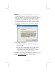
Installing Support Software 1.Insert the support CD-ROM disc in the CD-ROM drive. 2.When you insert the CD-ROM disc in the system CD-ROM drive, the CD automatically displays an Auto Setup screen. 3.The screen displays three buttons of Setup, Browse CD and Exit on the right side, and three others Setup, Application and ReadMe at the bottom. Please see the following illustration. The Setup button runs the software auto-installing program as explained in next section.
Auto-Installing under Windows 98/ME/2000/XP If you are under Windows 98/ME/2000/XP, please click the Setup button to run the software auto-installing program while the Auto Setup screen pops out after inserting the support CD-ROM: 1. The installation program loads and displays the following screen. Click the Next button. 2. Select the items that you want to setup by clicking on it (the default options are recommended). Click the Next button to proceed. 3. The support software will automatically install.
Installing under Windows NT or Manual Installation If you are under Windows NT, the auto-installing program doesn’t work out; or you have to do the manual installation, please follow this procedure while the Auto Setup screen pops out after inserting the support CD-ROM: 1. Click the ReadMe to bring up a screen, and then click the Install Path at the bottom of the screen. 2. Find out your mainboard model name and click on it to obtain its correct driver directory. 3.