Motherboard User’s Guide This publication, including photographs, illustrations and software, is under the protection of international copyright laws, with all rights reserved. Neither this user’s guide, nor any of the material contained herein, may be reproduced without the express written consent of the manufacturer. The information in this document is subject to change without notice.
Motherboard User’s Guide Table of Contents Trademarks .......................................................................................................... i Static Electricity Precautions ......................................................................................... i Pre-Installation Inspection ............................................................................................. i Chapter 1: Introduction .............................................................................
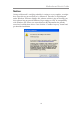
Motherboard User’s Guide Notice: Owing to Microsoft’s certifying schedule is various to every supplier, we might have some drivers not certified yet by Microsoft. Therefore, it might happen under Windows XP that a dialogue box (shown as below) pop out warning you this software has not passed Windows Logo testing to verify its compatibility with Windows XP. Please rest assured that our RD department has already tested and verified these drivers.
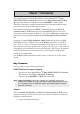
Chapter 1: Introduction Chapter 1 Introduction This motherboard has a LGA 775 socket for latest Intel® CoreTM2 Duo (E4XXX/E2XXX)/ Celeron® D processors with Hyper-Threading Technology and Front-Side Bus (FSB) speeds up to 1066/800/533 MHz. HyperThreading Technology, designed to take advantage of the multitasking features gives you the power to do more things at once.
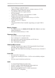
Motherboard User’s Guide • • • • • • System Memory Controller Support -Supports DDR2 SDRAM with up to maximum memory of 2 GB PCI Express Graphics Interface Support -One PCIEX16 slot for Graphic Interface PCI Bus Interface -Supports PCI Revision 2.3 Specification at 33 MHz Integrated Serial ATA Host Controller -Supports four ports with data transfer rate up to 3.0 Gb/s Integrated IDE Controller -Ultra ATA 100/66/33 Support USB 2.0 -Integrated USB 2.0 Host Controller supporting up to eight USB 2.
Chapter 1: Introduction Onboard I/O Ports • Two PS/2 ports for mouse and keyboard • One serial port • One VGA port • Four USB ports • One LAN port (optional) • Audio jacks for microphone, line-in and line-out Onboard LAN (optional) The onboard LAN controller provides the following features: • • • Integrated 10/100/1000 transceiver Supports PCI v2.
Motherboard User’s Guide Dimensions • Micro ATX form factor of 244 x 210 mm Note: Hardware specifications and software items are subject to change without notification. Package Contents Your motherboard package ships with the following items: The motherboard The User’s Guide One diskette drive ribbon cable (optional) One IDE drive ribbon cable The Software support CD Optional Accessories You can purchase the following optional accessories for this motherboard.
Chapter 2: Motherboard Installation Chapter 2 Motherboard Installation To install this motherboard in a system, please follow these instructions in this chapter: Identify the motherboard components Install a CPU Install one or more system memory modules Make sure all jumpers and switches are set correctly Install this motherboard in a system chassis (case) Connect any extension brackets or cables to headers/connectors on the motherboard Install peripheral devices and make the appropriate conn
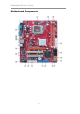
Motherboard User’s Guide Motherboard Components 6
Chapter 2: Motherboard Installation ITEM 1 LABEL CPU Socket COM PONENTS LGA 775 Soc ket f or Intel® Core™ 2 Duo (E4XXX/E2XXX)/ Celeron ® D CPUs 2 CPU_FA N CPU c ooling f an connec tor 3 4 DIMM1/2 A TX1 240-pin DDR2 SDRA M s lots Standard 24-Pin A TX Pow er connector 5 SA TA 1~4 Serial A TA connectors 6 F_USB1~2 Front Panel USB headers 7 SPK1 Speaker header 8 USBPWR_F Front Panel USB Pow er Selec t Jumper F_PA NEL1 Front panel s w itch/LED header 10 9 IDE1 Primary IDE c onnector 1
Motherboard User’s Guide I/O Ports The illustration below shows a side view of the built-in I/O ports on the motherboard. PS2 Mouse PS2 Keyboard Use the upper PS/2 port to connect a PS/2 pointing device. Use the lower PS/2 port to connect a PS/2 keyboard. Serial Port (COM1) Use the COM port to connect serial devices such as mice or fax/modems. COM1 is identified by the system as COM1. LAN Port (optional) Connect an RJ-45 jack to the LAN port to connect your computer to the Network.
Chapter 2: Motherboard Installation Installing the Processor This motherboard has a LGA775 socket for the latest Intel® CoreTM 2 Duo (E4XXX/E2XXX)/Celeron® D processors. When choosing a processor, consider the performance requirements of the system. Performance is based on the processor design, the clock speed and system bus frequency of the processor, and the quantity of internal cache memory and external cache memory. CPU Installation Procedure Follow these instructions to install the CPU: A.
Motherboard User’s Guide D. Install the CPU on the socket • Orientate CPU package to the socket. Make sure you match triangle marker to pin 1 location. E. Close the load plate • Slightly push down the load plate onto the tongue side, and hook the lever. • CPU is locked completely. F. Apply thermal grease on top of the CPU. G. Fasten the cooling fan supporting base onto the CPU socket on the motherboard. H. Make sure the CPU fan is plugged to the CPU fan connector.
Chapter 2: Motherboard Installation Memory Module Installation Procedure These modules can be installed with up to 2 GB system memory. Refer to the following to install the memory module. 1. Push down the latches on both sides of the DIMM socket. 2. Align the memory module with the socket. There is a notch on the DIMM socket that you can install the DIMM module in the correct direction. Match the cutout on the DIMM module with the notch on the DIMM socket. 3.
Motherboard User’s Guide Jumper Settings Connecting two pins with a jumper cap is SHORT; removing a jumper cap from these pins, OPEN. CLR_CMOS: Clear CMOS Jumper Use this jumper to clear the contents of the CMOS memory. You may need to clear the CMOS memory if the settings in the Setup Utility are incorrect and prevent your motherboard from operating. To clear the CMOS memory, disconnect all the power cables from the motherboard and then move the jumper cap into the CLEAR setting for a few seconds.
Chapter 2: Motherboard Installation Install the Motherboard Install the motherboard in a system chassis (case). The board is a Micro ATX size motherboard. You can install this motherboard in a Micro ATX case. Make sure your case has an I/O cover plate matching the ports on this motherboard. Install the motherboard in a case. Follow the case manufacturer’s instructions to use the hardware and internal mounting points on the chassis.
Motherboard User’s Guide Connecting Optional Devices Refer to the following for information on connecting the motherboard’s optional devices: F_AUDIO1: Front Panel Audio Header This header allows the user to install auxiliary front-oriented microphone and line-out ports for easier access.
Chapter 2: Motherboard Installation Here is a list of headers F_USB1/F_USB2 pin assignments. Pin 1 3 5 7 9 1 2 3 Signal USBPWR USB_FP_P0(-) USB_FP_P0(+) GND KEY Pin 2 4 6 8 10 Signal USBPWR USB_FP_P1(-) USB_FP_P1(+) GND USB_FP_OC0 Locate the F_USB1/F_USB2 headers on the motherboard. Plug the bracket cable onto the F_USB1/F_USB2 headers. Remove a slot cover from one of the expansion slots on the system chassis. Install an extension bracket in the opening.
Motherboard User’s Guide Install Other Devices Install and connect any other devices in the system following the steps below. Floppy Disk Drive The motherboard ships with a floppy disk drive cable that can support one or two drives. Drives can be 3.5" or 5.25" wide, with capacities of 360K, 720K, 1.2MB, 1.44MB, or 2.88MB. Install your drives and connect power from the system power supply. Use the cable provided to connect the drives to the floppy disk drive connector FDD.
Chapter 2: Motherboard Installation On the motherboard, locate the Serial ATA connectors SATA1-4, which support new Serial ATA devices for the highest data transfer rates, simpler disk drive cabling and easier PC assembly. It eliminates limitations of the current Parallel ATA interface, but maintains register compatibility and software compatibility with Parallel ATA.
Motherboard User’s Guide Expansion Slots This motherboard has one PCIEX16 slot and two 32-bit PCI slots. PCIEX16 Slot The PCIEX16 is used to install an external PCI Express graphics card that is fully compliant to the PCI Express Base Specification revision 1.0a. PCI 1~2 Slots This motherboard is equipped with two standard PCI slots. PCI stands for Peripheral Component Interconnect and is a bus standard for expansion cards, which for the most part, is a supplement of the older ISA bus standard.
Chapter 2: Motherboard Installation Follow these instructions to install an add-on card: 1 2 Remove a blanking plate from the system case corresponding to the slot you are going to use. Install the edge connector of the add-on card into the expansion slot. Ensure that the edge connector is correctly seated in the slot. 3 Secure the metal bracket of the card to the system case with a screw.
Motherboard User’s Guide Chapter 3 BIOS Setup Utility Introduction The BIOS Setup Utility records settings and information of your computer, such as date and time, the type of hardware installed, and various configuration settings. Your computer applies the information to initialize all the components when booting up and basic functions of coordination between system components. If the Setup Utility configuration is incorrect, it may cause the system to malfunction.
Chapter 3: BIOS Setup Utility You can use cursor arrow keys to highlight anyone of options on the main menu page. Press Enter to select the highlighted option. Press the Escape key to leave the setup utility. Press +/-/ to modify the selected field’s values. Some options on the main menu page lead to tables of items with installed values that you can use cursor arrow keys to highlight one item, and press + and - keys to cycle through alternative values of that item.
Motherboard User’s Guide f IDE Devices Your computer has one IDE channel which can be installed with one or two devices (Master and Slave). In addition, this motherboard supports two SATA channels and each channel allows one SATA device to be installed. Use these items to configure each device on the IDE channel. CMOS SETUP UTILITY – Copyright (C) 1985-2005, American Megatrends, Inc.
Chapter 3: BIOS Setup Utility Press to return to the Standard CMOS Setup page. Advanced Setup This page sets up more advanced information about your system. Handle this page with caution. Any changes can affect the operation of your computer. CMOS Setup Utility - Copyright (C) 1985-2005, American Megatrends, Inc. Advanced Setup CPU TM function Max CPUID Value Limit Execute Disable Bit Intel(R) SpeedStep(tm) tech.
Motherboard User’s Guide APIC Mode (Enabled) This item allows you to enable or disable the APCI (Advanced Programmable Interrupt Controller) mode. APIC provides symmetric multi-processing (SMP) for systems, allowing support for up to 60 processors. Boot Other Device (Enabled) When enabled, the system searches all other possible locations for an operating system if it fails to find one in the devices specified under the First, Second and Third boot devices.
Chapter 3: BIOS Setup Utility Share Memory Size (Enabled, 8MB) This item lets you allocate a portion of the main memory for the onboard VGA display application. Press to return to the main menu setting page. Integrated Peripherals This page sets up some parameters for peripheral devices connected to the system. CMOS Setup Utility - Copyright (C) 1985-2005, American Megatrends, Inc.
Motherboard User’s Guide Serial Port1 Address (3F8&IRQ4) Use this item to enable or disable the onboard COM1/2 serial port, and to assign a port address. Parallel Port Address (378) Use this item to enable or disable the onboard Parallel port, and to assign a port address. Parallel Port Mode (ECP) Use this item to select the parallel port mode. You can selet Normal (Standard Parallel Port), ECP (Extended Capabilities Port), EPP (Enhanced Parallel Port), or BPP (BiDirectional Parallel Port).
Chapter 3: BIOS Setup Utility PWRON After PWR-Fail (Power Off) This item enables your computer to automatically restart or return to its operating status. Resume On LAN (Disabled) This item allows users to enable or disable LAN activity to wake up the system from a power saving mode. Wake-Up by PME (Enabled) The system can be turned off with a software command. If you enable this item, the system can automatically resume if there is an incoming call on the PCI Modem or PCI LAN card.
Motherboard User’s Guide Init Display First (PCI Card) Use this item to select which graphics controller to use as the primary boot devices. Allocate IRQ to PCI VGA (Yes) If this item is enabled, an IRQ will be assigned to the PCI VGA graphics system. You set this value to No to free up an IRQ. Press to return to the main menu setting page. PC Health Status On motherboards support hardware monitoring, this item lets you monitor the parameters for critical voltages, temperatures and fan speeds.
Chapter 3: BIOS Setup Utility SMART Fan Control (Disabled) This item allows you to enable/disable the control of the system fan speed by changing the fan voltage. Press to return to the PC Health Status page. Shutdown Temperature (Disabled) Enable you to set the maximum temperature the system can reach before powering down.
Motherboard User’s Guide Ratio Actual Value These items show the locked ratio status and the actual ratio of the CPU installed in your system. CPU Frequency Setting (200 MHz) This item allows you to set CPU frequency. DRAM Frequency (Auto) This item shows the frequency of the DRAM in your computer. Auto Detect DIMM/PCI Clk (Enabled) When this item is enabled, BIOS will disable the clock signal of free DIMM/PCI slots.
Chapter 3: BIOS Setup Utility Supervisor Password (Not Installed) This item indicates whether a supervisor password has been set. If the password has been installed, Installed displays. If not, Not Installed displays. Change Supervisor Password (Press Enter) You can select this option and press to access the sub menu. You can use the sub menu to change the supervisor password. Press to return to the main menu setting page. User Password This page helps you install or change a password.
Motherboard User’s Guide Save & Exit Setup Highlight this item and press to save the changes that you have made in the Setup Utility and exit the Setup Utility. When the Save and Exit dialog box appears, select [OK] to save and exit, or select [Cancel] to return to the main menu. Exit Without Saving Highlight this item and press to discard any changes that you have made in the Setup Utility and exit the Setup Utility.
Chapter 4: Software & Applications Chapter 4 Software & Applications Introduction This chapter describes the contents of the support CD-ROM that comes with the motherboard package. The support CD-ROM contains all useful software, necessary drivers and utility programs to properly run our products. More program information is available in a README file, located in the same directory as the software. To run the support CD, simply insert the CD into your CD-ROM drive.
Motherboard User’s Guide The Browse CD button is a standard Windows command that you can check the contents of the disc with the Windows 98 file browsing interface. The Exit button closes the Auto Setup window. To run the program again, reinsert the CD-ROM disc in the drive; or click the CD-ROM driver from the Windows Explorer, and click the Setup icon. The Application button brings up a software menu. It shows the bundled software that this mainboard supports.
Chapter 4: Software & Applications 3 The support software will automatically install. Once any of the installation procedures start, software is automatically installed in sequence. You need to follow the onscreen instructions, confirm commands and allow the computer to restart as few times as needed to complete installing whatever software you selected. When the process is finished, all the support software will be installed and start working.
Motherboard User’s Guide Hyper-Threading CPU While you are in Windows Task Manager, please push down ctrl+Alt Del keys. A dual CPU appears in the CPU Usage History&Device Manager under WinXP. Note: Hyper-Threading Function only works under WINXP Operating System; therefore, disable it under other Operating System.