Motherboard User’s Guide This publication, including photographs, illustrations and software, is under the protection of international copyright laws, with all rights reserved. Neither this user’s guide, nor any of the material contained herein, may be reproduced without the express written consent of the manufacturer. The information in this document is subject to change without notice.
Motherboard User’s Guide Table of Contents Trademark ............................................................................................................ i Static Electricity Precautions ......................................................................................... i Pre-Installation Inspection ............................................................................................. i Chapter 1: Introduction ............................................................................
Motherboard User’s Guide Chapter 5: VIA VT8237 RAID Setup Guide .................................................. 37 VIA RAID Configuration ............................................................................................. 3 7 Installing RAID Software & Drivers ........................................................................... 4 5 Using VIA RAID Tool ...................................................................................................
Chapter 1: Introduction Chapter 1 Introduction This motherboard has a LGA775 socket for latest * Intel® CoreTM 2 Quad/ TM Intel® Core 2 Duo/Pentium® 4/Celeron® D processors with HyperThreading Technology and Front-Side Bus (FSB) speeds up to 1066 MHz. Hyper-Threading Technology, designed to take advantage of the multitasking features, giving you the power to do more things at once.
Motherboard User’s Guide Chipset There are P4M900 CD Northbridge and VT8237S in the chipsets in accordance with an innovative and scalable architecture with proven reliability and performance. • • • • • • • • High Performance Host Interface: Supports * Intel® CoreTM 2 Quad/ TM Intel® Core 2 Duo/Pentium® 4/Celeron® D processor family with FSB 1066 MHz Hyper-Threading Technology System Memory Controller Support: DDR2 SDRAM with up to maximum memory of 4 GB.
Chapter 1: Introduction Audio • • • • • 5.1Channel High Definition Audio Codec ADCs support 44.1k/48k/96k sample rate High-quality analog differential CD input Meet Microsoft WHQL/WLP 3.
Motherboard User’s Guide Package Contents Your motherboard package ships with the following items: The motherboard The User’s Guide One diskette drive ribbon cable (optional) One IDE drive ribbon cable The Software support CD Optional Accessories You can purchase the following optional accessories for this motherboard. The Extended USB module The CNR v.
Chapter 2: Motherboard Installation Chapter 2 Motherboard Installation To install this motherboard in a system, please follow these instructions in this chapter: Identify the motherboard components Install a CPU Install one or more system memory modules Make sure all jumpers and switches are set correctly Install this motherboard in a system chassis (case) Connect any extension brackets or cables to headers/connectors on the motherboard Install peripheral devices and make the appropriate conn
Motherboard User’s Guide Motherboard Components ITEM LABEL 1 CPU Socket COMPONENTS ® ® ® 2 CPU_FAN Pentium 4/Celeron D CPUs CPU cooling fan connector 3 DDRII1~2 240-pin DDR2 SDRAM slots 4 ATX1 Standard 24-pin ATX pow er connector 5 SATA1~2 Serial ATA connectors 6 BIOS_WP BIOS flash protect jumper 7 IDE1 Primary IDE connector 8 SPK1 Speaker header 9 IR1 Infrared header 10 PANEL1 Front panel sw itch/LED header 11 CLR_CMOS Clear CMOS jumper 12 USB3~4 14 Front Panel USB hea
Chapter 2: Motherboard Installation I/O Ports The illustration below shows a side view of the built-in I/O ports on the motherboard. PS/2 Mouse Use the upper PS/2 port to connect a PS/2 pointing device. PS/2 Keyboard Use the low er PS/2 port to connect a PS/2 keyboard. COM1 Use the COM port to connect serial devices such as mice or fax/modems. COM1 is identified by the system as COM1. VGA Port Use the VGA port to connect VGA devices.
Motherboard User’s Guide Installing the Processor This motherboard has a LGA775 socket for the latest * Intel® CoreTM 2 Quad/ TM Intel® Core 2 Duo/Pentium® 4/Celeron® D processors. When choosing a processor, consider the performance requirements of the system. Performance is based on the processor design, the clock speed and system bus frequency of the processor, and the quantity of internal cache memory and external cache memory. CPU Installation Procedure Follow these instructions to install the CPU: A.
Chapter 2: Motherboard Installation E. Close the load plate • Slightly push down the load plate onto the tongue side, and hook the lever. • CPU is locked completely. F. Apply thermal grease on top of the CPU. G. Fasten the cooling fan supporting base onto the CPU socket on the motherboard. H. Make sure the CPU fan is plugged to the CPU fan connector. Please refer to the CPU cooling fan user’s manual for mor detail installation procedure.
Motherboard User’s Guide Memory Module Installation Procedure These modules can be installed with up to 4 GB system memory. Refer to the following to install the memory module. 1. Push down the latches on both sides of the DIMM socket. 2. Align the memory module with the socket. There is a notch on the DIMM socket that you can install the DIMM module in the correct direction. Match the cutout on the DIMM module with the notch on the DIMM socket. 3.
Chapter 2: Motherboard Installation CLR_CMOS: Clear CMOS Jumper Use this jumper to clear the contents of the CMOS memory. You may need to clear the CMOS memory if the settings in the Setup Utility are incorrect and prevent your motherboard from operating. To clear the CMOS memory, disconnect all the power cables from the motherboard and then move the jumper cap into the CLEAR setting for a few seconds.
Motherboard User’s Guide Install the Motherboard Install the motherboard in a system chassis (case). The board is a Micro ATX size motherboard. You can install this motherboard in an ATX case. Make sure your case has an I/O cover plate matching the ports on this motherboard. Install the motherboard in a case. Follow the case manufacturer’s instructions to use the hardware and internal mounting points on the chassis. Connect the power connector from the power supply to the ATX1 connector on the motherboard.
Chapter 2: Motherboard Installation Connecting Optional Devices Refer to the following for information on connecting the motherboard’s optional devices: SPK1: Speaker Header Connect the cable from the PC speaker to the SPK1 header on the motherboard.
Motherboard User’s Guide F_AUDIO1: Front Panel Audio Header This header allows the user to install auxiliary front-oriented microphone and line-out ports for easier access. Pin 1 3 5 7 9 Signal PORT1L PORT1R PORT2R SENSE_SEND PORT2L Pin 2 4 6 8 10 Signal GND PRESENCE# Sense1_return KEY Sense2_return USB3/USB4: Front panel USB Headers The motherboard has USB ports installed on the rear edge I/O port array. Additionally, some computer cases have USB ports at the front of the case.
Chapter 2: Motherboard Installation LPT1: Onboard parallel port Header This header allows the user to connect to the printer, scanner or devices.
Motherboard User’s Guide Floppy Disk Drive The motherboard ships with a floppy disk drive cable that can support one or two drives. Drives can be 3.5" or 5.25" wide, with capacities of 360 K, 720 K, 1.2 MB, 1.44 MB, or 2.88 MB. Install your drives and connect power from the system power supply. Use the cable provided to connect the drives to the floppy disk drive connector FDD1. IDE Devices IDE devices include hard disk drives, high-density diskette drives, and CD-ROM or DVD-ROM drives, among others.
Chapter 2: Motherboard Installation Analog Audio Input Connector If you have installed a CD-ROM drive or DVD-ROM drive, you can connect the drive audio cable to the onboard sound system. When you first start up your system, the BIOS should automatically detect your CD-ROM/DVD drive. If it doesn’t, enter the Setup Utility and configure the CD-ROM/DVD drive that you have installed. On the motherboard, locate the 4-pin connector CD_IN1.
Motherboard User’s Guide Expansion Slots This motherboard has one PCI Ex16, one PCI Ex1 and two 32-bit PCI slots.
Chapter 2: Motherboard Installation Follow the steps below to install an PCI Express/CNR/PCI expansion card. 1 Locate the PCI Express, CNR or PCI slots on the motherboard. 2 Remove the blanking plate of the slot from the system chassis. 3 Install the edge connector of the expansion card into the slot. Ensure the edge connector is correctly seated in the slot. 4 Secure the metal bracket of the card to the system chassis with a screw.
Motherboard User’s Guide Chapter 3 BIOS Setup Utility Introduction The BIOS Setup Utility records settings and information of your computer, such as date and time, the type of hardware installed, and various configuration settings. Your computer applies the information to initialize all the components when booting up and basic functions of coordination between system components. If the Setup Utility configuration is incorrect, it may cause the system to malfunction.
Chapter 3: BIOS Setup Utility Some options on the main menu page lead to tables of items with installed values that you can use cursor arrow keys to highlight one item, and press PgUp and PgDn keys to cycle through alternative values of that item. The other options on the main menu page lead to dialog boxes requiring your answer OK or Cancel by selecting the [OK] or [Cancel] key. If you have already changed the setup utility, press F10 to save those changes and exit the utility.
Motherboard User’s Guide Advanced Setup Page This page sets up more advanced information about your system. Handle this page with caution. Any changes can affect the operation of your computer. CMOS Setup Utility – Copyright (C) 1985-2005, American Megatrends, Inc.
Chapter 3: BIOS Setup Utility f Hard Disk Drives (Press Enter) Scroll to this item and press to view the following screen: CMOS Setup Utility – Copyright (C) 1985-2005, American Megatrends, Inc. Hard Disk Drives Help Item Hard Disk Drives 1st FLOPPY DRIVE WDC WD2500JS-08NCB1 1st Drive 2nd Drive Specifies the boot sequence from the available devices. : Move Enter: Select +/-/: Value F10: Save Esc: Exit F1: General Help F9: Optimized Defaults Press to return to Advanced Setup screen.
Motherboard User’s Guide Boot Other Device When enabled, the system searches all other possible locations for operating system if it fails to find one in the devices specified under the First, Second, and Third boot devices. BIOS Protect This item enables or disables BIOS protect. Press to return to the main menu page. Advanced Chipset Setup Page This page sets up more advanced chipset information about your system. Handle this page with caution. Any changes can affect the operation of your computer.
Chapter 3: BIOS Setup Utility Integrated Peripherals Page This page sets up some parameters for peripheral devices connected to the system. CMOS Setup Utility – Copyright (C) 1985-2005, American Megatrends, Inc.
Motherboard User’s Guide HDAC Audio Controller Use this item to enable or disable the onboard Audio controller. LAN Controller This option allows you to enable or disable the onboard LAN controller. LAN Option ROM Use this item to enable or disable the booting from the onboard LAN with a remote boot ROM installed. Onboard USB Function Enable this item if you plan to use the USB ports on this motherboard.
Chapter 3: BIOS Setup Utility Resume On RTC Alarm The system can be turned off with a software command. If you enable this item, the system can automatically resume at a fixed time based on the system’s RTC (realtime clock). Use the items below this one to set the date and time of the wake-up alarm. You must use an ATX power supply in order to use this feature. Resume On Ring The system can be turned off with a software command.
Motherboard User’s Guide PCI / PnP Setup Page This page sets up some parameters for devices installed on the PCI bus and those utilizing the system plug and play capability. CMOS Setup Utility – Copyright (C) 1985-2005, American Megatrends, Inc.
Chapter 3: BIOS Setup Utility System Component Characteristics These fields provide you with information about the system current operating status. • • • • • • CPU Temperature System Temperature CPU Fan Speed System Fan Speed CPU Vorce VDIMM CPU SMART Fan Control This item allows users to enable or disable smart fan control function. Press to return to the main menu setting page. Frequency/Voltage Control Page This page helps you to set the clock speed and system bus for your system.
Motherboard User’s Guide CPU Over-clocking Func. This item decides the CPU over-clocking function/frequencyinstalled in your system. If the over-clocking fails, please turn offthe system power. And then, hold the PageUp key (similar to theClear CMOS function) and turn on the power, the BIOS willrecover the safe default. CPU Frequency This item indicates the current CPU frequency. Users can not make any change to this item. Please noted that the frequency will be varied with different CPU.
Chapter 3: BIOS Setup Utility Change Supervisor Password You can select this option and press to access the sub menu. You can use the sub menu to change the supervisor password. Press to return to the main menu setting page. User Password Page This page helps you set up some parameters for the hardware monitoring function of this motherboard. CMOS Setup Utility – Copyright (C) 1985-2005, American Megatrends, Inc.
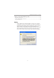
Motherboard User’s Guide Chapter 4 Software & Applications Introduction This chapter describes the contents of the support CD-ROM that comes with the motherboard package. The support CD-ROM contains all useful software, necessary drivers and utility programs to properly run our products. More program information is available in a README file, located in the same directory as the software. To run the support CD, simply insert the CD into your CD-ROM drive.
Chapter 4: Software & Applications The Exit button closes the Auto Setup window. To run the program again, reinsert the CD-ROM disc in the drive; or click the CD-ROM driver from the Windows Explorer, and click the Setup icon. The Application button brings up a software menu. It shows the bundled software that this mainboard supports. The ReadMe brings you to the Install Path where you can find out path names of software driver.
Motherboard User’s Guide 3 The support software will automatically install. Once any of the installation procedures start, software is automatically installed in sequence. You need to follow the onscreen instructions, confirm commands and allow the computer to restart as few times as needed to complete installing whatever software you selected. When the process is finished, all the support software will be installed and start working.
Chapter 4: Software & Applications Follow these instructions to Disable Vista UAC function: 1. Go to Control Panel. 2. Select Classic View. 3. Set User Account.
Motherboard User’s Guide 4. Select Turn User Account Control on or off and press Continue. 5. Disable User Account Control (UAC) to help protect your computer item and press OK, then press Restart Now. Then you can restart your computer and continue to install drivers without running blocked programs. Bundled Software Installation All bundled software available on the CD-ROM is for users’ convenience.
Chapter 5: VIA VT8237 SATA RAID Setup Guide Chapter 5 VIA VT8237 SATA RAID Setup Guide VIA RAID Configurations The motherboard includes a high performance Serial ATA RAID controller integrated in the VIA VT8237 Southbridge chipset. It supports RAID 0, RAID 1 and JBOD with two independent Serial ATA channels. RAID: (Redundant Array of Independent Disk Drives) use jointly several hard drives to increase data transfer rates and data security.
Motherboard User’s Guide Follow these steps to install the SATA hard disks for RAID configuration. i Before setting up your new RAID array, verify the status of your hard disks. Make sure the Master/Slave jumpers are configured properly. ii Both the data and power SATA cables are new cables. You cannot use older 40-pin 80-conductor IDE or regular IDE power cables with Serial ATA drives.
Chapter 5: VIA VT8237 SATA RAID Setup Guide On the upper-right side of the screen is the message and legend box. The keys on the legend box allow you to navigate through the setup menu options. The message describes the function of each menu item. The following lists the keys found in the legend box with their corresponding functions.
Motherboard User’s Guide 4 Select Block Size, then press to set array block size. Lists of valid array block sizes are displayed on a pop-up menu. Tip For server systems, it is recommended to use a lower array block size. For multimedia computer systems used mainly for audio and video editing, a higher array block size is recommended for optimum performance. Use arrow keys to move selection bar on items and press to select.
Chapter 5: VIA VT8237 SATA RAID Setup Guide 3 4 5 Select task and press . The screen returns to Create Array menu items. From this point, you may choose to auto-configure the RAID array by selecting Auto Setup for Data Security or manually configure the RAID array for mirrored sets. If you want to manually configure the RAID array continue with next step, otherwise, proceed to step #5. Select Select Disk Drives, then press .
Motherboard User’s Guide Serial Number View 1 In the VIA RAID BIOS utility main menu, select Serial Number View then press the key. The focus is directed to the list of channel used for IDE RAID arrays. Move the selection bar on each item and the serial number is displayed at the bottom of the screen. This option is useful for identifying same model disks.
Chapter 5: VIA VT8237 SATA RAID Setup Guide Rebuild Broken RAID 1 Array When booting up the system, BIOS will detect if any member disk drives of RAID has failed or is absent. If BIOS detects any disk drive failures or missing disk drives, the status of the array will be marked as broken. If BIOS detects a broken RAID 1 array but there is a spare hard drive available for rebuilding the broken array, the spare hard drive will automatically become the mirroring drive.
Motherboard User’s Guide 3. Choose Replacement Drive and Rebuild: This item enables users to select an already-connected hard drive to rebuild the broken array. After choosing a hard drive, the channel column will be activated. Highlight the target hard drive and press , a warning message will appear. Press Y to use that hard drive to rebuild, or press N to cancel. Please note selecting option Y will destroy all the data on the selected hard drive. 4.
Chapter 5: VIA VT8237 SATA RAID Setup Guide Installing RAID Software & Drivers Install Driver in Windows OS New Windows OS (2000/XP/NT4) Installation The following details the installation of the drivers while installing Windows XP. 1 Start the installation: Boot from the CD-ROM. Press F6 when the message “Press F6 if you need to install third party SCSI or RAID driver’ appears. 2 When the Windows Setup window is generated, press S to specify an Additional Device(s).
Motherboard User’s Guide Installation of VIA SATA RAID Utility The VIA SATA RAID Utility is the software package that enables highperformance RAID 0 arrays in the Windows*XP operating system. This version of VIA SATA RAID Utility contains the following key features: • Serial ATA RAID driver for Windows XP • VIA SATA RAID utility • RAID0 and RAID1 functions Insert the supported CD and click on the Setup to install the software. The InstallShield Wizard will begin automatically for installation.
Chapter 5: VIA VT8237 SATA RAID Setup Guide Put a check mark in the check box to install the feature you want. Then click Next button to proceed the installation. Using VIA RAID Tool Once the installation is complete, go to Start---> Programs---> VIA---> raid_tool.exe to enable VIA RAID Tool. After the software is finished installation, it will automatically started every time Windows is initiated.
Motherboard User’s Guide The main interface is divided into two windows and the toolbar above contain the main functions. Click on these toolbar buttons to execute their specific functions. The left windowpane displays the controller and disk drives and the right windowpane displays the details of the controller or disk drives.
Chapter 5: VIA VT8237 SATA RAID Setup Guide Click on the plus (+) symbol next to Array 0--RAID 0 to see the details of each disk. You may also use the same Array 0--RAID 1.
Motherboard User’s Guide Click on the plus (+) symbol next to Array 0; RAID 1 to see the details of each disk.