
User`s guide


12
Motherboard User’s Guide
Pin Signal Pin Signal
1 HD_LED_P( +) 2 FP PWR/SLP(+)
3 HD_LED_N(-) 4 FP PWR/SLP(-)
5 RES ET_SW_N( - ) 6 POWER_SW_P( +)
7 RES ET_ SW _P( +) 8 POWER_ SW _N( - )
9 RSV D_DNU 10 KEY
Here is a list of the PANEL1 pin assignments.
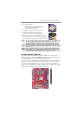
Install the Motherboard
Install the motherboard in a system chassis (case). The board is a Micro ATX
size motherboard. You can install this motherboard in an ATX case. Make sure
your case has an I/O cover plate matching the ports on this motherboard.
Install the motherboard in a case. Follow the case manufacturer’s instructions to
use the hardware and internal mounting points on the chassis.
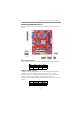
Connect the power connector from the power supply to the ATX1 connector on
the motherboard. The ATX_12V1 is a +12V connector for CPU Vcore power.
If there is a cooling fan installed in the system chassis, connect the cable from the
cooling fan to the SYS_FAN fan power connector on the motherboard.
Connect the case switches and indicator LEDs to the PANEL1 header.