ADSL2+ Full-Rated Router User’s Manual Sept 2006
Copyright Copyright © 2004 by this company. All rights reserved. No part of this publication may be reproduced, transmitted, transcribed, stored in a retrieval system, or translated into any language or computer language, in any form or by any means, electronic, mechanical, magnetic, optical, chemical, manual or otherwise, without the prior written permission of this company.
Contents 1. Introduction ................................................................................................5 1.1 System Requirements ................................................................................ 5 1.2 Package Contents....................................................................................... 5 2. Product Features .......................................................................................5 2.1 ADSL Compliant .......................................
5.5 5.6 5.7 5.8 5.4.3 PPP....................................................................................................... 48 5.4.4 EDA ...................................................................................................... 50 5.4.5 IPOA ..................................................................................................... 52 Bridging..................................................................................................... 53 5.5.1 Bridging .........
.8.9 Backup/Restore Configuration.......................................................... 96 5.8.10 Management Control .......................................................................... 98 5.8.11 Autodetect ........................................................................................... 99 5.8.12 SNMP Configuration ......................................................................... 100 5.8.13 Parental Control ..............................................................
1. Introduction This ADSL2+ Ethernet router is a full-featured ADSL router that provides high-speed Internet access and Ethernet direct connections to individual PCs or local area network with 10/100 Base-T Ethernet. This ADSL2+ router uses advanced ADSL chipset solution with complete set of industry standard features and high-speed ADSL, ADSL2 and ADSL2+ network solution for SOHO and residential users.
z ITU-T G.992.5 (ADSL2+) z Reach Extended ADSL (RE ADSL) z Auto-negotiating rate adaptation 2.2 ATM Protocols and Encapsulations z ATM Forum UNI 3.1 / 4.0 PVC z Support up to 8 VCs (Virtual Circuit) z ATM SAR (Segmentation and Reassembly) z Traffic Shaping UBR, CBR, VBR-nrt z Multi Protocol over AAL5 (RFC1483 / 2684) z RFC 1577 (Classical IP over ATM) z VC and LLC Multiplexing z VPI is 0-255 and VCI is 32-65535 z OAM F4 and F5 segment end-to-end loopback 2.
z CHAP (Challenge Authentication Protocol; RFC1994) z User authentication for PPP z Password Protected System Management z Firewall 2.7 Device management z Firmware upgrade via FTP / TFTP (Web-based) z SNMP MIB Support z WAN and LAN connection statistics z Selection of Bridge or Router Mode z Configuration of VCs (Virtual Circuits) 2.8 Interface z Compliant with USB v1.1, full speed (12Mbps) z One or Four RJ45 port compatible with IEEE 802.3/802.
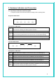
3. Hardware Indicators and Connectors 3.1 Front Panel Indicators and Description Front panel of ADSL router has LED indicators to display router’s operating status. Single-Port ADSL Router ○ ADSL ○ ○ ○ ○ DATA LAN USB PWR Descriptions of LED status ADSL DATA LAN When connection with Internet (ADSL Connected) is established, this LED will light up. When this LED is flashing: NO ADSL physical connection When router is transferring data between Internet and router, this LED will be flashing.
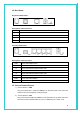
3.2 Back Panel Single-Port ADSL Router LINE USB LAN PWR DEFAULT Descriptions of All Connectors LINE Connect with telephone line. USB Connect with USB cable. LAN Connect with Ethernet Cable to Switch Hub or PC PWR Connect with power adapter DEFAULT Reset button. Four-Port ADSL Router LINE USB 1X 2X 3X 4X PWR DEFAULT Descriptions of All Connectors LINE Connect with telephone line. USB Connect with USB cable. 1x Connect with Ethernet Cable to Switch Hub.
3) Connect Router to Power Adapter Plug power adapter to PWR port on the back panel of the router and the other end to a power outlet. The diagram below illustrates a connection example, Warning! Only use the power adapter provided in the package, otherwise it may cause hardware damage.
4. Connecting ADSL Router via Ethernet and USB You can connect this ADSL Router with PC through Ethernet cable or USB cable. After connect is established, you can configure the host PC to be a DHCP client. You have to repeat the same steps for every host PC on your network if you user DHCP function on your router. 4.1 Setup ADSL router via Ethernet Cable If there is an available LAN card present on your PC, you just simply connect ADSL router and PC through the Ethernet cable.
Step 3: Insert “Easy Setup” Software kit CD, and then click “Install USB Driver” to begin device driver installation. Step 4: After “DSL Modem Setup Wizard” shows, click “Next” to continue.
Step 5: Please review the following license agreement, and click “Accept” to continue. Step 6: Waiting for few seconds for device driver installation.
Step 7: For completing your installation, the DSL Modem Setup Wizard requires to reboot your system. Please choose “Yes, reboot the computer now” and click “Close” for reboot. Step 8: After you restart your computer, you can see Finish windows. Click “Finish” to compete the installation.
Step 9: Follow the procedures below to check if DSL router is properly installed. Right-click “My Computer” on the desktop Æ Choose “Properties” Æ Select “Hardware” tab Æ Click “Device Manager” button. 4.3 TCP/IP Configuration For Windows XP Step 1: Click Start and then select Control Panel in the main window screen.
Step 2: Double-Click Network Connections icon. Step 3: Right-click Local Area Connection (local network your ADSL hooked up with) and then select “Properties”.
Step 4: Select Internet Protocol (TCP/IP) then click “Properties”. Configure IP address Automatically: Step 5: Select Obtain an IP address automatically & Obtain DNS server address automatically.
Configure IP address Manually: Step 5: Select Use the following IP address & Use the following DNS server addresses. IP address: Fill in IP address 192.168.1.x. (x is a number between 3 to 254). Subnet Mask: Default value is 255.255.255.0. USB interface Default gateway: Default value is 192.168.1.2. Ethernet interface Default gateway: Default value is 192.168.1.1 Preferred DNS server: Fill in preferred DNS server IP address. Alternate DNS server: Fill in alternate DNS server IP address.
If the communication link between your computer and router is not setup correctly, after your type ping 192.168.1.2 under DOS prompt following message will appear. Pinging 192.168.1.2 with 32 bytes of data: Request timed out. Request timed out. Request timed out. Request timed out. This failure might be caused by cable issue or something wrong in configuration procedure. For Windows 2000 Step 1: Right-click My Network Places and select Properties in the main windows screen.
Step 3: Select Internet Protocol (TCP/IP) then click Properties.
Configure IP Automatically: Step 4: Select Obtain an IP address automatically and Obtain DNS server address automatically then click OK to complete IP configuring process. Configure IP Manually: Step 4: Select Use the following IP address and Use the following DNS server addresses.
IP address: Fill in IP address 192.168.1.x. (x is a number between 3 to 254). Subnet Mask: Default value is 255.255.255.0. USB interface Default gateway: Default value is 192.168.1.2. Ethernet interface Default gateway: Default value is 192.168.1.1 Preferred DNS server: Fill in preferred DNS server IP address. Alternate DNS server: Fill in alternate DNS server IP address. For Windows 98SE/ME Step 1: Click Start then Settings and choose Control Panel Step 2: Double click Network icon.
Option1: Get an IP from Router Automatically 1) Choose Obtain an IP address automatically option in the next window.
3) Select DNS Configuration tab and select Disable DNS then click OK Option2: Configure IP Manually 1) Select Specify an IP address, set default IP address for the Router is 192.168.1.2, so use 192.168.1.X (X is a number between 3 to 254) for IP Address field and 255. 255. 255.0 for Subnet Mask field.
2) Select Gateway tab and add default Router IP Address (USB interface default gateway: 192.168.1.2, Ethernet interface default gateway: 192.168.1.1) in the New gateway field and click Add. 3) Under DNS Configuration tab, select Enable DNS and add DNS values which provides by your local ISP in DNS Server Search Order field then click Add.
4.4 Setup ADSL Router via USB Cable on MAC Step 1: Once you insert the Device Driver CD-ROM disk, direct the path of your MAC OS. You will see “DO-407952-LS-3.zip” file. Copy this file to Macintosh HD. Step 2: After you copy the zip file to Macintosh HD, double-click the compressed “.zip” file to unzip it. You will get “IAD_Rel_1_02E_PKG_004.sit” file. Step 3: Double-click “.sit” file. The “IAD_Rel_1_02E_PKG_004.1” file will be created. Double-click the created file again to open it.
Step 5: The ADSL Modem Installer window will be shown. Click “Next” to continue. Step 6: Enter your Name and password for your system. Then, click “OK” to continue.
Step 7: Please review the License Agreement below and click “Accept” if you agree with the license agreement. Step 8: After the installation is finished, you must restart your computer before using your modem. Click “Finish” to restart your computer.
Step 9: After restart your computer, click “System Preferences” on the bottom of the desktop. Step 10: Click “Network” icon on the System Preferences windows. Step 11: Once your Ethernet Adapter’s button is “Green”, it means your DSL Router is successful installed.
Step 12: Fill in TCP/IP IP Address: IP address: Fill in IP Address 192.168.1.x. ( x is a number between 3 to 254). Subnet Mask: Default value is 255.255.255.0. Router: Default value is 192.168.1.2.
Step 13: Choose “Application” on GO menu. Double-click “Internet Explorer”. Step 14: Enter the default IP address: http://192.168.1.2 Step 15: Entry of the User ID and Password will be displayed. Enter the default User ID and Password. The default login User ID of the administrator & the default administrator login Password are “root”. Then, click “OK” to enter.
Step 16: DSL Router Webpage will show as below: 4.5 Setup ADSL Router via USB Cable on Linux This driver supports Linux-2.4 kernel. Compiling the Driver To compile the driver simply run make in "viking" directory. This will create binary driver with name VKGEther. % make Loading the module To load the VKGEther module enter the following command as root in directory "viking" Syntax: % insmod .
interface name is eth1 in above line. LAN Configuration To enable LAN traffic over the ethernet interface: % ifconfig eth1 192.168.1.200 up You may also need to modify the netmask and route for the interface. Refer to the manual pages for ifconfig and route for more information. To test the LAN connection is alive by pinging the remote side: % ping 192.168.1.1 To disconnect the LAN interface: % ifconfig eth1 down 5.
5.2 Home The Home page displays when you first access the program or, if another tab is already displaying, when you click on the Home tab. 5.2.1 Home The System View table provides a snapshot of the device configuration. Note that some of the settings are links to the software pages that enable you to configure those settings.
Device: Displays basic information about the device hardware and software versions, the system uptime since the last reboot, and the preconfigured operating mode. DSL: Displays the operational status, DSL standard conformance, and performance statistics for the DSL line. You can click DSL in the table heading to display additional DSL settings. WAN Interfaces: Displays the software name(s) and settings for the device interfaces that communicate with the ISP via DSL, such as a PPP, EOA, or IPoA interface.
Message forwarding based on the Internet Group Management Protocol (IGMP, not z configurable). 5.2.2 System Mode The System Mode page enables you to configure system-level operating modes that use bridging in addition or instead of routing protocols. You can also configure a feature in which the mode is selected automatically at start-up, based on the type of Internet connection detected on the LAN PC(s).
5.2.3 Quick Configuration The Quick Configuration displays the settings you are most likely to need to change when you first set up your ADSL/Ethernet router. Work with your ISP to determine the values or settings you need to change. NOTE: It is a strong recommendation that using Quick Configuration to set your ADSL settings. z ATM Interface: Selects the ATM interface you want to use (usually 0).
z VPI and VCI: Determine the unique data path your modem uses to communicate with your ISP. z Bridge: Enables or disables bridging between the device and your ISP. z IGMP: Can be used to enable the WAN interface to pass Internet Group Management Protocol messages it receives to the LAN PCs. You must enable the LAN or USB interfaces for IGMP. z IP Address and Subnet Mask: If your ISP has provided a public IP address to your LAN, enter the address and the associated subnet mask in the boxes provided.
5.3 LAN 5.3.1 LAN Configuration Use this page to set the LAN configuration, which determines how your device is identified on the network. The LAN Configuration table displays the following settings: z System Mode: Identifies the system operating mode for your device, such as Routing mode, Bridging mode, or both modes simultaneously. See Configuring the System Mode for more information).
-- Manual indicates that you will be assigning a static IP address, which you can enter in the fields below. -- External DHCP Server indicates that your ISP will be assigning an IP address from their own DHCP servers, dynamically each time you log on. -- Internal DHCP Server indicates that you have a DHCP server device on your network that will assign an address to the port. If you choose either the internal or external server option, the LAN interface is called a DHCP client of the server.
5.3.2 DHCP Mode You can configure your network and ADSL/Ethernet router to use the Dynamic Host Configuration Protocol (DHCP). This help topic provides an overview of DHCP and instructions for implementing it on your network. DHCP is a protocol that enables network administrators to centrally manage the assignment and distribution of IP information to computers on a network. The device can be configured as a DHCP server, relay agent, or client.
5.3.3 DHCP Server This topic describes how to configure the DHCP server feature on your ADSL/Ethernet router. Adding DHCP Server Address Pools: 1. If the DHCP Server Configuration page is not already displaying, click the LAN tab, and then click DHCP Server in the task bar. Depending on your pre-configured settings, the table may display up to two address pools, each in a row, or may be empty. 2. Click Add. The DHCP Server Pool - Add page displays. 3.
that corresponds to this MAC address. If you type a MAC address here, you must have specified the same IP address in both the Start IP Address and End IP Address fields. Net Mask: Specifies which portion of each IP addresses in this range refers to the z network and which portion refers to the host (computer). You can use the net mask to distinguish which pool of addresses should be distributed to a particular subset of computers on your LAN (call a subnet).
Follow these instructions to configure DHCP relay: First, you must configure each LAN computer to receive IP information assigned by a DHCP server: 1) Open the Windows Control Panel and display the computer's Networking properties. Configure the TCP/IP properties to "Obtain an IP address automatically" (the actual text may vary depending on your operating system). Next, you specify the IP address of the DHCP server and select the interfaces on your network that will be using the relay service.
4) Select your WAN interface from the drop-down list and click Add. The WAN interface may be named ppp-0, eoa-0, or ipoa-0. Contact your ISP if you are unsure which type to use. (Note that you can delete an interface from the table by clicking in the right column.) 5) Click Submit. A page displays to confirm your changes, and the program returns to the DHCP Relay Configuration page. 6) Click DHCP Mode in the task bar, then follow the instructions in Setting the DHCP Mode to enable DHCP relay.
5.4 WAN 5.4.1 DSL The DSL Status page displays current information on the DSL line performance. The page refreshes according to the setting in the Refresh Rate drop-down list, which you can configure. [DSL Status] In the DSL Status table, the Operational Status setting displays a red, orange, or green ball to indicate that the DSL line is idle, starting up, or up-and-running, respectively. You can click Loop Stop to end the DSL connection. To restart the connection, you can click Loop Start.
parameters page, which provides data about the configuration of the DSL line. You cannot modify this data. The DSL Parameters and Status table displays settings preconfigured by the product z manufacturer or your ISP. The Config Data table lists various types of error and defect measurements found on the z DSL line. [DSL Statistics] From the DSL Status page, you can click Stats to display DSL line performance statistics.
interface names are preconfigured in the software and identify the type of traffic that can be supported, such as data or voice. Internet data services typically use an AAL5-type interface.
You can configure the following settings on the PPP Configuration page: Inactivity TimeOut...: The time in minutes that must elapse before a PPP connection times-out due to inactivity. This setting applies only to PPP interfaces that are configured as "start-on-data" interfaces. This type of interface starts up only when it receives data, and then returns to a down state after the specified amount of time.
listed on the DHCP Server Configuration page). Use DNS: When set to Enable, the DNS address learned through the PPP connection will be distributed to clients of the device's DHCP server. This option is useful only when the ADSL/Ethernet Router is configured to act as a DHCP server for your LAN. When set to Disable, LAN hosts will use the DNS address(es) pre-configured in the DHCP pool and in the DNS feature. Oper.
defined in the software. z A private interface connects to your LAN, such as the Ethernet interface. Packets received on a private interface are subject to a less restrictive set of protections, because they originate within the network. z The term DMZ (de-militarized zone), in Internet networking terms, refers to computers that are available for both public and in-network accesses (such as a company's public Web server).
5.4.5 IPOA This topic describes how to configure an IPoA (Internet Protocol over ATM) interface on the ADSL/Ethernet router. Interface: The name the software uses to identify the IPoA interface. Interface Security Type: The type of firewall protections that are in effect on the interface (public, private, or DMZ): z A public interface connects to the Internet (IPoA interfaces are typically public).
"lower level" functions (i.e., closer to hardware) than the IPoA interface. Peer IP Address: The IP address of the remote computer you will be connecting to via the WAN interface. Config IP Address and Net Mask: The IP address and network mask you want to assign to the interface. Gateway Address: The external IP address that the ADSL/Ethernet router communicates with via the IPoA interface to gain access to the Internet. This is typically an ISP server.
[Enabling Bridgeable Interfaces] To enable bridging, you use the Bridge Configuration page to specify the interfaces that can bridge data. Then, you use the System Mode page to enable the appropriate operating mode. 1. If the Bridge Configuration page is not already displaying, click the Bridging tab. The Bridge Configuration Page displays by default. The page displays Enable/Disable links for Bridging, WAN-to-WAN Bridging, and Zero Installation PPP bridge (ZIPB).
The LAN Configuration table displays the following settings: System Mode: Identifies the system operating mode for your device, such as Routing mode, Bridging mode, or both modes simultaneously. Get LAN Address: Provides options for how the device's LAN interface is assigned an IP address. z Manual indicates that you will be assigning a static IP address, which you can enter in the fields below.
that will assign an address to the port. If you choose either the internal or external server option, the LAN interface is called a DHCP client of the server. Note that the public IP address assigned to you by your ISP is not your LAN IP address. The public IP address identifies the WAN (ADSL) port on your ADSL/Ethernet router to the Internet. Or, in bridge configurations, it may be assigned to a PC.
[DSL Status] The DSL Status page displays current information on the DSL line performance. The page refreshes according to the setting in the Refresh Rate drop-down list, which you can configure. In the DSL Status table, the Operational Status setting displays a red, orange, or green ball to indicate that the DSL line is idle, starting up, or up-and-running, respectively. You can click Loop Stop to end the DSL connection. To restart the connection, you can click Loop Start.
[DSL Parameters] From the DSL Status Page, you can click DSL Param to display the DSL parameters page, which provides data about the configuration of the DSL line. You cannot modify this data.
[DSL Statistics] From the DSL Status page, you can click Stats to display DSL line performance statistics. The DSL Statistics page reports error data relating to the current 15 minute interval, the current day, and the previous day. 5.5.4 ATM VC The devices WAN-side interfaces are used to communication via the DSL port.
virtual circuit (VC) properties of the ATM VC interface identify a unique path that your ADSL/Ethernet router uses to communicate via the ATM-based network with the telephone company central office equipment. z The higher-level protocol interface(s) operate "on top" of the ATM VC interface. The higher-level interface handles the protocols needed to log onto and exchange data with the ISP's access server.
5.5.5 RFC 1483 Interface (EoA) The Ethernet-over-ATM (EoA) protocol is commonly used to carry data between local area networks that use the Ethernet protocol and wide-area networks that use the ATM protocol. Many telecommunications industry networks use the ATM protocol. ISPs who provide DSL services often use the EoA protocol for data transfer with their customers' DSL modems. EoA can be implemented to provide a bridged connection between a DSL modem and the ISP.
that are available for both public and in-network accesses (such as a company's public Web server). Packets incoming on a DMZ interface -- whether from a LAN or external source -- are subject to a level of protection that is in between those for public and private interfaces. Lower interface: EoA interfaces are defined in software, and then associated with lower-level software and hardware structures (at the lowest level, they are associated with a physical port - the WAN port).
Destination: Specifies the IP address of the destination computer. The destination can specified as the IP address of a specific computer or an entire network. It can also be specified as all zeros to indicate that this route should be used for all destinations for which no other route is defined (this is the route that creates the default gateway). Netmask: Indicates which parts of the destination address refer to the network and which parts refer to a computer on the network.
5.6.2 IP Address Table The interfaces on your ADSL/Ethernet router that communicate with other network and Internet devices are identified by unique Internet protocol (IP) addresses. You can use the Configuration Manager to view the list of IP addresses that your device uses, and to view other system and network performance data. The IP Address table lists the IP addresses, network masks ("Net Mask"), and interface names ("IF Name") for each of its IP-enabled interfaces. 5.6.
If you are using the ADSL/Ethernet router with multiple PCs on your LAN, you must connect the LAN via an Ethernet hub connected to the device's LAN port. If you are using a single PC with the ADSL/Ethernet router, you have two connection options: z You can connect the PC directly to the LAN port using a cross-over Ethernet cable. See your User's Manual for a description of cross-over and straight-through Ethernet cables. z If the PC is USB-enabled, you can connect it directly to the device's USB port.
Bridging mode, or both modes simultaneously. Get LAN Address: Provides options for how the device's LAN interface is assigned an IP address: Manual indicates that you will be assigning a static IP address, which you can enter in the z fields below. External DHCP Server indicates that your ISP will be assigning an IP address from their z own DHCP servers, dynamically each time you log on.
In the DSL Status table, the Operational Status setting displays a red, orange, or green ball to indicate that the DSL line is idle, starting up, or up-and-running, respectively. You can click Loop Stop to end the DSL connection. To restart the connection, you can click Loop Start. 5.6.5 ATM VC The devices WAN-side interfaces are used to communication via the DSL port.
virtual circuit (VC) properties of the ATM VC interface identify a unique path that your ADSL/Ethernet router uses to communicate via the ATM-based network with the telephone company central office equipment. z The higher-level protocol interface(s) operate "on top" of the ATM VC interface. The higher-level interface handles the protocols needed to log onto and exchange data with the ISP's access server.
5.6.6 PPP The Point-to-Point Protocol (PPP) is one of several protocols used to enable communication between ISPs and their customers. PPP performs tasks such as the following: z Identifying the type of service the ISP provides to a given customer. z Identifying the customer to the ISP through a username and password login. z Enabling the ISP to assign Internet information to the customer's computers. You can configure the following settings on the PPP Configuration page: Inactivity TimeOut...
VC: The Virtual Circuit over which this PPP data is sent. The VC identifies the physical path the data takes to reach your ISP. Interface Sec Type: The type of Firewall protections that are in effect on the interface (public, private, or DMZ): z A public interface connects to the Internet (PPP interfaces are typically public). Packets received on a public interface are subject to the most restrictive set of firewall protections defined in the software.
5.6.7 EOA This topic describes how to configure an Ethernet-over-ATM (EoA) interface on the ADSL/Ethernet router, if one is needed to communicate with your ISP. This interface is also commonly referred to as an RFC1483 interface, for the name of the Internet specification to which it conforms.
- the WAN port). This field should reflect an interface name defined in the next lower level of software over which the EoA interface will operate. This will be an ATM VC interface, such as aal5-0 Config IP Address and Net Mask: The IP address and network mask you want to assign to the interface. If the interface will be used for bridging with your ISP and you will not be using the device as a router on your LAN, then you do not need to specify IP information.
Interface: The name the software uses to identify the IPoA interface. Interface Security Type: The type of firewall protections that are in effect on the interface (public, private, or DMZ): z A public interface connects to the Internet (IPoA interfaces are typically public). Packets received on a public interface are subject to the most restrictive set of firewall protections defined in the software. z A private interface connects to your LAN, such as the Ethernet interface.
Config IP Address and Net Mask: The IP address and network mask you want to assign to the interface. Gateway Address: The external IP address that the ADSL/Ethernet router communicates with via the IPoA interface to gain access to the Internet. This is typically an ISP server. Status: A green or red ball will display to indicate that the interface is currently up or down, respectively.
The NAT Global Information table, which displays the following settings that apply to all NAT rule translations: TCP Idle Timeout (sec), TCP Close Wait (sec), TCP Def Timeout (sec): When two z computers communicate via the Internet, a Transmission Control Protocol-based communication session is created between them to control the exchange of data packets.
The following instructions describe how to enable RIP on your ADSL/Ethernet router: (1) If the RIP Configuration page is not already displaying, click the Services tab, and then click RIP in the task bar. The page contains radio buttons for enabling or disabling the RIP feature and a table listing interfaces on which the protocol is currently running. The first time you open this page, the table may be empty (2) If necessary, change the Age and Update Time.
corresponding ppp, eoa, or other WAN interface. (4) Select a metric value for the interface RIP uses a "hop count" as a way to determine the best path to a given destination in the network. The hop count is the sum of the metric values assigned to each port through which data is passed before reaching the destination. Among several alternative routes, the one with the lowest hop count is considered the fastest path (5) Select a Send Mode and a Receive Mode.
Black List Status: If you want the device to maintain and use a black list, click Enable. Click Disable if you do not want to maintain a list. Black List Period(min): Specifies the number of minutes that a computer's IP address will remain on the black list (i.e., all traffic originating from that computer will be blocked from passing through any interface on the ADSL/Ethernet router).
z Land Attack: Sending packets that use the same address as the source and destination address z Ping of Death: Illegal IP packet length. DoS Protection: Click the Enable radio button to use the following denial of service protections: Max Half open TCP Connection: Sets the percentage of concurrent IP sessions that can be in the half-open state.
Security Level: This setting determines which IP Filter rules take effect, based on the security level specified in each rule. For example, when High is selected, only those rules that are assigned a security value of High will be in effect. The same is true for the Medium and Low settings. When None is selected, IP Filtering is disabled.
Accept, so that LAN computers have access to the ADSL/Ethernet routers' Internet connection. The term DMZ (de-militarized zone), in Internet networking terms, refers to computers z that are available for both public and in-network accesses (such as a company's public Web server). Packets received on a DMZ interface -- whether from a LAN or external source -- are subject to a set of protections that is in between public and private interfaces in terms of restrictiveness.
with system-defined rules. It is also recommended that you assign rule IDs in multiples of 5 or 10 (e.g., 1000, 1010, 1020) so that you leave enough room between them for inserting new rules if necessary. Interface: The interface on which the rule will take effect. Direction: Specifies whether the rule should apply to packets that are incoming or outgoing on the selected interface. Incoming refers to packets coming in to the LAN on the interface, and Outgoing refers to packets going out from the LAN.
Multiple DNS addresses are useful to provide alternatives when one of the servers is down or is encountering heavy traffic. ISPs typically provide primary and secondary DNS addresses, and may provide additional addresses. Your LAN PCs learn these DNS addresses in one of the following ways: Statically: If your ISP provides you with their DNS server addresses, you can assign the z addresses to each PC by modifying the PCs' IP properties.
PPPoE: Point to Point Protocol over Ethernet. Many DSL modems use PPoE to establish and maintain a connection with a service provider. PPoE provides a means of logging in to the ISPs servers so that they can authenticate you as a customer and provide you access to the Internet. Check with your ISP before blocking this protocol. IP Multicast: IP Multicast is an extension to the IP protocol.
LANs. BPDU: Bridge Protocol Data Unit. BPDUs are data messages that are exchanged across the switches between LANs that are connected by a bridge. BPDU packets contain information on ports, addresses, priorities and costs, and are exchanged across bridges to detect and eliminate loops in a network. ARP: Address Resolution Protocol. Computers on a LAN use ARP to learn the hardware addresses (i.e.
5.7.9 UPnP The UPnP Page is used to enable/disable UPnP feature for the next boot of the system. Save configuration and reboot the modem for the changes to take effect. 5.7.10 SNTP This SNTP page is used to enable/disable SNTP features as well as to view, add, and modify SNTP configuration.
5.8 Admin 5.8.1 User Configuration Configuration Manager is configured with a default user name and password combination, or login. If you want to allow other users to access the program, you can create additional user logins and specify their privilege levels. You can also change the password for the default login or for any logins you create.
5.8.2 Commit & Reboot This page allows user to commit configuration changes to permanement memory and reboot the device.
[Committing Changes] Whenever you use the configuration program to change system settings, the changes are initially placed in temporary storage called random access memory or RAM. Your changes are made effective when you submit them, but can be lost if the device is reset or turned off. You can commit changes to save them permanently to flash memory. [Rebooting the Device] To reboot the device from the Commit & Reboot page, select a reboot mode from the drop-down menu, and then click Reboot.
Follow this procedure if you have obtained an updated image from your ISP and stored the file on your PC, CD-ROM, or other media. 1. Insert the media containing the file in your PC's CD-ROM/disk drive. You can access the file from there or copy it to your hard drive or to any shared network drive. The name of the upgrade file must be either TEImage*.bin or TEPatch*.bin, where * represents any number of characters. 2.
When loading is complete, the following message displays (the file name may differ) Æ File: TEImage.bin successfully saved to flash. Please reboot for the new image to take effect. 5. Turn power to the unit off, wait a few seconds, and turn it on again. 5.8.4 Remote Image Upgrade Your ISP may from time to time notify you that a software upgrade is available. Upgrade files may be provided to you in two ways: z On a CD-ROM or other media.
3. In the Upgrade File text box, type the complete name of the file to be downloaded and loaded to flash, as indicated by your ISP. The name of the upgrade file must be either TEImage*.bin or TEPatch*.bin, where * represents any of additional characters, up to a total filename length of 256 characters. 4. In the Username and Password fields, type the information required to log on the ISP's server (if the ISP requires it). 5. Click Upload. An alert window pops up displaying the following message: 6.
-- You can click on the Refresh Rate drop-down list to select a recurring time interval after which the page will redisplay with new data. -- You can click Save Alarm to display a Windows File Download dialog box that enables opening or saving the contents of the log to your PC. The file is assigned the default name alarm.vlf, and can be viewed with any text editor. -- To remove all entries from the list, click Clear. New entries will begin accumulating and will display when you click Refresh. 5.8.
Follow these instructions to begin the diagnostic tests: (1) If the Diagnostics page is not currently displayed, click the Admin tab, and then click Diagnostics in the task bar. (2) From the WAN Interface drop-down list, select the name of the WAN interface on which the diagnostics are to be run. (3) Click Submit. (4) The diagnostics utility will run a series of tests to check whether the device's connections are up and working. This will take only a few seconds.
5.8.7 Port Settings The header information in an IP data packet specifies a destination port number. Routers use the port number along with the IP addresses to forward the packet to its intended recipient. Follow these steps to modify port settings: (1) If the Port Settings page is not already displaying, click the Admin tab, and then click Port Settings in the task bar. (2) Type the new port number(s) in the appropriate text box(es) and click Submit.
improper functioning and is not captured by the system traps that create alarm. You can click Save Log to display a Windows File Download dialog box that enables opening or saving the contents of the log to your PC. The file is assigned the default name syslog.vlf, and can be viewed with any text editor. To remove all entries from the list, click Clear Log. New entries will begin accumulating and will display when you click Refresh. 5.8.
settings with default values. Before you load the new image, you can store the configuration settings. Then, after you load the image, you can restore your previous configuration. Follow these instructions to save and restore the configuration file: (1) Ensure that any changes you have made in the current session have been committed (click the Admin tab, click Commit & Reboot in the task bar, and then click Commit). (2) In the Admin tab, click Backup/Restore Config in the task bar.
When the system reboots, your connection to the configuration program will be suspended and may appear to hang. If you want to continue to use Configuration Manager, wait about 30 seconds and Refresh the browser window (e.g., press if using Internet Explorer). You may need to log in again. 5.8.10 Management Control You can enable access to Configuration Manager from the WAN port so that the ISP can perform configuration tasks. The table on this page provides a check box to enable or disable HTTP (i.e.
5.8.11 Autodetect Autodetect enables the modem to automatically detect and configure a valid ATM VC at startup. Autodetect eliminates the need to have users configure VC values as described in Configuring the ATM Virtual Circuit [Autodetect Modes] Autodetect can be used to establish PPPoE, PPPoA, IPoA-1577 and EoA connections and can be configured in either of two modes: bridging mode and routing mode.
(3) Click the Enable radio button. (4) Click Submit. A page will display briefly to confirm your changes. Autodetect will not start searching for a valid connection until the modem is rebooted. (5) Click Reset. A warning message will display to inform you that the current configuration will be lost. (6) Click OK. The modem will reboot and the Web-based interface will be temporarily unavailable.
A complete SNMP setup includes the following items: -- A management station equipped with an SNMP manager client that enables sending messages to an SNMP agent (e.g., the modem). This configuration is not described here. -- A MIB stored in the modem's memory. This must be preconfigured in the software image by the ISP. -- The SNMP service enabled on the modem, including defined communities that allow read-only or read/write accesses from specific hosts. This configuration is described below.
5.8.13 Parental Control The Parental Control feature enables management users to block Internet access from specified LAN hosts for specified periods Follow these steps to block a host from accessing the Internet: (1) Ensure that either the system time is specified directly or SNTP is enabled. (2) If the Parental Control page is not already displaying, click the Admin tab and then click Parental Control in the menu bar.
If you have any troubles to configure or setup this ADSL Ethernet Router, please contact us. Before contacting us, make sure collect following information. Submit complete detailed information of your problem will help us to provide you accurate answers.