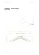
Fritz Building Instruction December 2020 BUILDING INSTRUCTION Flying wing Fritz Wing span [mm]: 1500 Wing area [dm2]: 24 Aspect ratio: Take-off weight [g]: Wing loading [g/dm²]: Airfoil: www.pcm.at 9,4 about 550 22,9 Strake from th=6,5/c=1,5 to sym.
Fritz Building Instruction December 2020 CONTENTS DATA 1. Kit – contents 2. What else do you need? 3. Electronic equipment 3 3 3 ASSEMBLING THE MODEL 4. Wing 4.1 Controlling ailerons and outer controls 5. Switch and charging plug 6. Receiver antenna 7. Tuning 4 4 9 10 10 OTHER 8. CG and aileron deflections 9. Notes for use 9.1 Starting with a bungee www.pcm.
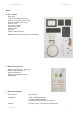
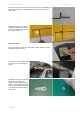
Fritz Building Instruction December 2020 DATA 1. Kit – contents Flying wing Lever for controlling ailerons, 2 pc. Parts for moving outer controls, 2 sets Rods for controlling ailerons 2 pc. Contacts 1 pair Gap covers for aileron Twisted servo cable Carbon covers Latex skin Steel for switch (not in pic) Building instruction (for download from our website) 2. What else do you need: Runny CA (cyanacrylat, = super glue) Electric equipment (plugs...
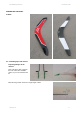
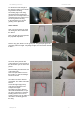
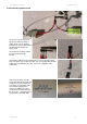
Fritz Building Instruction December 2020 ASSEMBLING THE MODEL 4. WING 4.1 Controlling flaps and ailerons Preparing linkages to the ailerons First of all, put a drop of CA into the hole of the horn and drill it again. So you can avoid the bad fit. Bend the long 1.2mm steel rod at a right angle at 6mm. www.pcm.
Fritz Building Instruction December 2020 Then you can put it into the hole of the lever and save it from falling out with the shrinking tube. This shrinking tube you can also save with a drop of CA. Prepare the lever slot for gluing. Grind it till the lacquer is removed. Then you can glue the lever into the slot with runny CA. Fixing the servos First of all prepare the surfaces, which will be glued. Grind them with a rough paper (grain size 80).
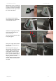
Fritz Building Instruction December 2020 Set the servo to zero position. The real zero position of the X08 servos is 1520 not 1500. Fix the aileron in zero position and transfer the hole position of the servo lever to the steel rod. Bend the steel at this point in a right angle, cut it at about 4mm behind and put it into the lever hole. Then fix the wooden frame with just some spots of CA. Remove the servo and glue every edge extensively. Set back the servo into the frame.
Fritz Building Instruction December 2020 To achieve the best strength of the wing the carbon cover should be glued into the fitting. The leading edge of the wing sometimes dashes against the ground. So it is heavily loaded. To avoid damages, the carbon cover has to be glued to the wing. In the first picture you see the grinding of the depression. Outer controls Here you see the parts you need for moving the outer control with the aileron. First of all, glue the green part into the prepared depression.
Fritz Building Instruction December 2020 With the help of the second green part you can mark the area, which you have to prepare for the gluing. Grind this area well. Prepare also the areas at the aileron. Put enough CA to the gluing areas and place the carbon part accurately with tweezers. Grind the next gluing areas well. Don´t forget to grind also the areas on the steel. Save the kevlar hinge with a tape from getting glued.
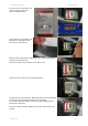
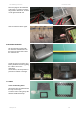
Fritz Building Instruction December 2020 5. SWITCH AND CHARGING PLUG The space for receiver and cell will also be closed by gluing a carbon sheet over the opening. Therefore we need a small device for switching and loading the battery pack. The solution is as follows. Solder the wires as shown in the pictures. The charging cable has to be soldered like you see in the right picture. Keep care of the way you plug it in when you are charging.
Fritz Building Instruction December 2020 Put in the plug into the milled slot of the wing. Let it stand out of the wing surface about 1mm, so that it can be glued well with CA. Here the switch is shown again. 6. RECEIVER ANTENNA We recommend receivers with two antennas. Drill two holes on the lower and upper side to lead the antennas out. At last the space for receiver and battery should be closed by gluing the carbon cover to the depression.
Fritz Building Instruction December 2020 Glue the frame to the latex foil and cut it out. We delivered twice as much latex as you need. So leave a piece for changing. Turn the frame with the foil so that the latex is on the upper side and glue it with tape into the depression of the wing. At the right picture you see the gripping position for a hand start. Covering gaps Cover the gaps with the sealing tape. Also cover the gap between the two controls at the lower side with the broad sealing tape.
Fritz Building Instruction 8. CG AND AILERON DEFLECTIONS December 2020 The CG should be set from 126mm to 128mm. - CG at 126mm is for slower flights (thermal flights). It is besides the safer CG, as Fritz sometimes shows a nod (one to multiple times nose down) at this CG, when you fly too slowly. What you see more often is yawing during aileron deflection when you are too slow. - CG at 128mm is for dynamic flights, for instance at good conditions on a slope.
Fritz Building Instruction December 2020 Aileron deflections www.pcm.
Fritz Building Instruction December 2020 9. NOTES FOR USE Things Fritz hates: - Starting with backwind. With the bungee it is possible, but not when starting with the hand. - Flying through turbulances, for instance behind trees. You have to be quick to do this without getting problems. - Flying into a lee side. With enough speed it is possible, but keep care. - Landing on the wingtips. Pay attention during landing. The wing has to be always parallel to the ground.