
Integration Guide


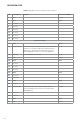
Table Of Contents
- Cover
- Table of Contents
- Tables and Figures
- Text Format Conventions
- Terms and Abbreviations
- Referenced Documents
- 1. Overview
- 2. Architecture
- 3. Connectors
- 4. Software Integration
- 5. Mechanical
- 6. Compliance
- 6.1. Manufacturer’s Federal Communication Commission (FCC) Compliance Statements
- 6.1.1. Antenna Information
- 6.1.2. FCC Declaration of Conformity Statement
- 6.1.3. FCC Radiation Exposure Statement
- 6.1.4. Factors Affecting Module Usage Related to FCC Compliance
- 6.2. Manufacturer’s Innovation, Science and Economic Development (ISED) Canada Compliance Statements
- 6.2.1. Antenna Information
- 6.2.2. ISED (Canada) Compliance Statement
- 6.2.3. ISED Canada Radiation Exposure Statement
- 6.2.4. Factors Affecting Module Usage Related to ISED Compliance
- 6.2.4. Limites d'utilisation du module liées à la conformité ISED
- 6.3. Manufacturer’s European Union (EU) and United Kingdom (UK) Compliance Statements
- 6.3.1. EU and UK Declaration of Conformity
- 6.3.2. Antenna Information
- 6.3.3. European Union and UK Radiation Exposure Statement
- 6.3.4. EU and UK Compliance Statement
- 7. Safety Notices
- Industrial IoT Product Usage

10
INTEGRATION GUIDE
Pin Description Legend Direction on Radio
2 3.3V Power
4 GND GND
6 Unused
8 Unused
10 Unused
12 Unused
14 Unused
16 Unused
Mechanical Key
18 GND GND
20 W_Disable1# Active low signal. Used by the system to disable radio
operation on cards that implement radio frequency
applications. (This has been implemented on the
PCTEL RM-WIFI-2x2-HP. Connected to GPIO18).
Input
22 PERST# Functional Reset to the card Input
24 3.3V Power
26 GND GND
28 Unused
30 Unused
32 Unused
34 GND GND
36 Unused
38 Unused
40 GND GND
42 Unused
44 LED_WLAN# Open drain, active low signal for LED indication of
status (Tied low for boot strap; connected to QCA
9898 GPIO017)
Output
46 Unused
48 Unused
50 GND GND
52 3.3V Power
Table 2. Mini PCIe connector pinout for the even pins